 |
ENGINEERED
STEEL PRODUCTS |
| Priced
Full Line Products Catalog |
20
Technology Way • West Greenwich, RI 02817
Toll free:(800) 421-0314 • In RI:(401) 272-4570 • Fax:(401)
421-5679 |
|
|
|
|
Back
to Product Category
| |
Standard
"Quick-Ship" Modular Offices
|
|
|
|
|
|
Installation
Instructions
|
|
|
|
|
|
|
Important:
We advise a thorough reading of these instructions before
beginning installation.
|
|
|
|
|
|
|
|
Introduction
|
|
|
|
|
|
|
|
|
|
Instructions
should be read thoroughly and cross-referenced with your job
drawings prior to commencing
installation.
Standard "Quick-Ship" Modular Offices are manufactured
from high quality materials with care taken in handling
and packing at the factory. Please inspect your materials
and count them to make sure that damage or loss has not
occurred in transit. Please notify us promptly if you experience
any problems. Review the accompanying Bill of
Materials and parts drawings to familiarize yourself with
the components of the system. Care must be exercised in
handling these materials. The framing parts are made from
painted steel and anodized aluminum. The material,
while strong and durable, will scratch, bend and/or mar. Normal
care in erection will result in a finished product of
which we both will be proud.
|
|
|
|
|
|
|
|
|
|
Tool
Suggestions
|
|
|
|
|
|
|
|
|
|
•
Hammer
• Rubber Mallet & Wood Block
• Electric Drill
• #30 Drill Bits (3 or 4)
• Phillip's Screwdriver
• 12 Ga. Extension Cord
• Putty Knife or Trowel (4" Blade)
• Level (30"or Longer)
|
|
•
Plumb Bob
• Chalk Line & Dry Line
• Tape Measure or Ruler
• Tin snips
• Pliers
• Hacksaw
• Pencil
• Ladder |
|
•
Carpenter's Square
• 9/16" Socket w/Ratchet
• 9/16" Wrench
• 5/16" Drive Socket
• 3/8" Drive Socket
• Fiberboard Knife
• Broom |
|
|
|
|
|
|
|
|
|
Unpacking,
Inspection & Inventory
|
|
|
|
|
|
The
Modular Office wall system is packaged in the factory in a
manner to protect each part during normal shipping
and handling. It is recommended that the original packaging
remain intact as much as possible until the individual
parts are needed. All extrusion components are typically packaged
in boxes. Panels are shipped with a foam
interleaf between panels.
As the skids are received at the job-site, they should be
placed in a location near the installation area, where they
will not become an obstacle, or require to be moved at a later
time. The skids should then be opened, however
leaving the internal packaging unchanged. Pieces can be removed
on an as needed basis and the packaging
discarded then. At this time the components should be visually
inspected for obvious damage and an inventory
taken to confirm that all parts are received as expected.
Notify us immediately of any discrepancies.
|
|
|
|
|
|
Fasteners
Not Provided
|
|
|
|
|
|
The
attachment hardware for the floor track to the flooring and
wall starters to existing structures are not included
due to installer preferences, local codes, and varying flooring
and ceiling systems.
The following are recommendations:
• Concrete floor: powder
actuated fasteners: heavy duty dome head nail – type
DS 1-1/4" long
• Wood floor: 1/4"
x 1" lag bolt
• Steel floor: #14 x 1"
sheet metal screws
• Drywall: 1/4" toggle
bolts, drywall or wood screws
|
|
|
|
|
|
Installer
Tip!
|
|
|
|
|
|
To
save time, mark the centerlines of all the studs on the floor
in front of the floor track. This will assist you in
maintaining the centerlines shown on the drawings.
|
|
|
|
|
|
Floor
Track Installation
|
|
|
|
|
|
|
|
|
|
|
|
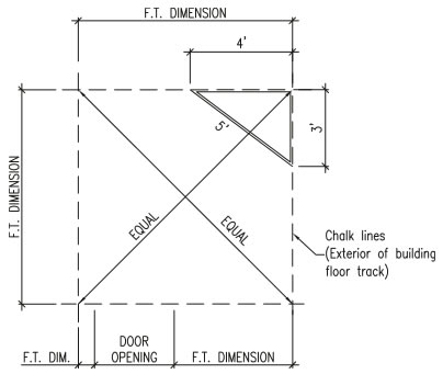
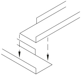
Step
1
Locate the first wall and strike a chalk line
on the floor. This line is the outside edge of your
floor track.
Step 2 Lay out the floor track per floor plan
drawings. Cut floor track length as noted by F.T.
dimensions on the drawing. Use metal snips to cut
the floor track lengths. Note: Use the 3 - 4 - 5
triangle method or a carpenter's square to confirm
90° corners. (Detail A)
Step 3 Mark wiring stud centerlines & door
openings per plans. (Note: It is imperative that
stud centerlines be maintained.)
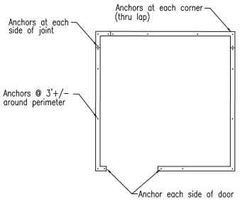
Step 4 Notch corner locations (Detail B) to allow
ends to lap each other.
Step 5 Refer to (Detail C) when securing floor
track to surface with floor anchors.
|
|
 |
|
|
|
Detail
A - Floor Plan
|
|
|
|
|
|
|
|
|
|
|
|
|
|
 |
|
|
|
|
 |
|
|
|
|
|
|
|
Detail
B - Corner Lap Detail
|
|
|
|
Detail
C - Floor Track Layout
|
|
|
|
|
|
|
|
|
|
|
|
|
Pre-Assemble
Stud Posts
|
|
|
|
|
|
|
|
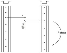
The
holes of a stud hat have an offset pattern that allows two
identical hats to
be secured together by rotating one of the hat sections. This
alignment will
offset the holes, allowing the standard #10-16 x 3/4"
Tek 2 screw to use a pre-punched hole on one hat and to tap
through the opposing hat. (Detail D)
Assemble stud posts. Leave out the cover strips until Step
#8 of Electrical
Section.
Screw the stud sections together leaving the sections loose
enough to install
the panel.
|
|
 |
|
|
|
Detail
D
|
|
|
|
|
|
|
|
|
|
|
|
The
holes of a Series 300 stud hat are prepunched on both sides
of the raceway at 12" o.c. Assemble stud assembly by inserting
Part A into Part B. Using a #10-16 x 3/4" Tek 2 screw fasten
the two parts together using a prepunched hole on Part A to
tap through the opposing Part B. |
|
|
|
|
|
|
|
Wall
Erection
|
|
|
|
|
|
|
|
|
|
|
|
|
|
Wall
panels are fabricated and ready to install. Standard wall
panels are 44-7/8" wide and are interchangeable with
other full panels, windows and door panels. Special width
filler panels (F.P.) are labeled on floor plan.
Step 6 Check the floor for level. In extreme cases
(out of level by 1/2" or more) select the high corner
as your
starting point. If possible, leave the door panel to be installed
last. Shimming may be necessary if floor surface is
not very level.
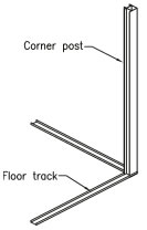
Step 7 Begin wall installation by inserting a corner
post into the floor track (Detail E). Note:
the corner post is
inside both the vertical legs of the floor track. The corner
post should be loosely assembled using Phillip's flat head
1/4"-14 x 3/4" screws to allow install of panel.
|
|
|
|
|
|
|
|
|
|
 |
|
|
|
|
 |
|
 |
|
|
|
|
|
|
|
|
|
|
|
Detail
G
|
|
|
|
|
|
|
|
|
|
|
|
|
|
|
|
|
Installer
Tip!
|
|
|
|
|
|
|
|
|
|
|
|
|
|
|
|
When
installing the panels into the stud, pull the panel back on
one corner and slide the other
corner into the stud or corner. |
|
|
|
|
|
|
|
|
|
|
Detail
E
|
|
Detail
F
|
|
|
|
|
|
|
|
|
|
|
|
|
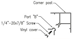
Step
8
Install the two adjacent corner wall panels into the floor
track and slide gently into corner post (Detail F). Tighten
the
corner post screws and install vinyl corner inserts (Detail
G). |
|
|
|
|
|
|
|
|
|
|
Installation
Note
|
|
|
|
|
|
|
|
|
|
Do
NOT push panel all the way into the stud. Hold centerline dimension. |
|
|
|
|
|
|
|
|
|
|
Step
9 Install
pre-assembled studs next to each panel.
Check centerline dimension of stud to corner post from your
floor plan.
Tighten screws after panel is in place (Detail H).
Refer to the fastener guide for screws required. Do not over
tighten screws.
|
|
|
|
|
|
|
Detail
H
|
|
|
|
 |
|
|
|
|
|
|
|
|
|
Load-Bearing
Office
|
|
|
|
|
|
|
|
|
|
|
Install
a 10 gauge bearing plate inside the floor track below
each stud and corner. Use 3-3/16" x 5" plate for studs
and
4-1/2" x 4-1/2" notched plate for corners. |
|
|
|
|
|
|
|
|
|
|
|
|
 |
|
|
|
|
Step
10
Assemble mitered
cornice mold corner assembly
(Detail I). Each standard corner includes two short pieces
of
cornice mold with one end
mitered. These special pieces
will be used to make your
cornice mold corners. If corner
to stud dimensions is less than
50-1/4", field cut the cornice
mold so that the end not mitered falls on the centerline of
the
stud. Secure cornice mold
corners to the interior side of
the corner post w/ #10-16 x 3/4"
Tek 3 screws.
Step 11 Insert next panel into
floor track; slide into stud and
tighten screw. (Note: Do not
over tighten screws). Continue toward next corner. Check each
panel for plumb (Detail J). |
|
|
|
|
|
|
|
|
 |
|
|
|
|
|
|
Detail
J
1. Check stud
for plumb.
2. Check wall
for plumb.
|
|
|
|
|
|
|
|
|
|
Detail
I
|
|
|
|
|
|
|
|
|
|
|
|
|
|
|
|
|
|
|
|
|
Step
12
Check the centerline dimension of each stud with the dimensions
on your floor plan. This will eliminate any growth or shrinkage
of the overall dimension.
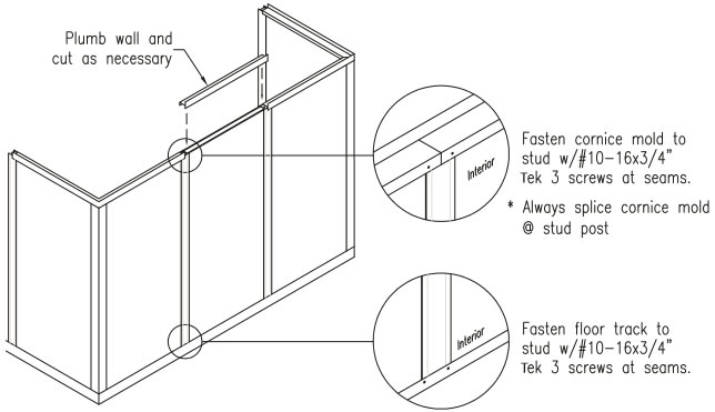
Step 13 Set cornice mold in place. If necessary, cut
the cornice mold so that it fits between the two cornice mold
corners you have assembled.
Step 14 Recheck the wall and corners for plumb. Secure
the stud through the cornice mold and floor track on the interior
side of wall at each stud location with #10-16 x 3/4"
Tek 3 screws (Detail K).
Step
15
Install the remaining walls in the same manner.
|
|
|
|
 |
|
|
|
|
Detail
K
|
|
|
|
|
|
|
|
|
Window
Panels
|
|
|
|
 |
|
|
|
|
|
|
|
|
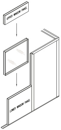
Window
panels install into the stud in the same manner as the wall
panels.
Step 16 Insert the lower window panel in the adjacent stud.
(Detail L)
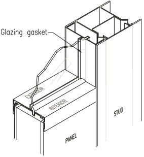
Step 17 Install the window onto the lower window panel
with the gasket to
the inside of the room. (Detail M) Handle with care. |
|
|
|
|
|
|
|
|
|
|
|
|
 |
|
|
|
|
Detail
L
|
|
|
Detail
M
|
|
|
|
|
|
|
|
|
|
|
|
Step
18
Insert the upper window panel. (Detail L)
Step 19 Slide on the adjacent stud and proceed with the
next panel.
Note: To prevent breakage, we recommend the window be
moved only in an upright position with the bottom
supported.
For a neat job, make certain that the window frames are inserted
completely into the studs and the sill heights
align. If the wall consists of many window units it is imperative
the windows be inserted all the way into the studs
and you check your centerline dimension of your studs to make
sure they match the drawing; otherwise the wall
will grow in length and the last unit will not fit into the
corner. |
|
|
|
|
|
|
|
|
|
|
Vinyl
Base
|
|
|
|
|
|
|
|
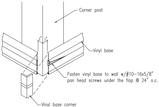
Step
20 The screw on vinyl base should be cut to fit for the
interior and exterior of the room. Lift cover flap and
secure to wall with #10-16 x 5/8" pan head screws at
24" centers. Push the cover strip in, to lock in place,
and
cover screw heads. Pre-formed exterior corners are supplied
for the outside corners only. (Detail N)
|
|
|
|
 |
|
|
|
|
|
|
|
|
|
Detail
N
|
|
|
|
|
|
|
|
|
Single
Door Installation
|
|
|
|
|
|
|
|
|
|
|
|
The
door and frame come pre-installed in a full size wall panel.
Handle door assembly panel with care and lift the
panel from the sides, not the ends. |
|
|
|
|
|
|
|
|
|
|
|
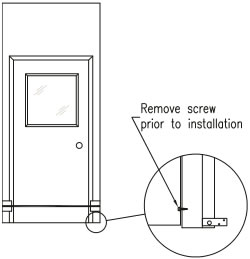
Step
1 For handling purposes, the bottom of the door is fastened
to the
door frame. This must be removed before installing the door
assembly
panel. Also verify at this point that the floor track opening
is 37-3/8".
(Detail O)
Install the door assembly panel into the floor track. The
floor track will fit between the door frame and the panel.
Be sure the wall with the door is
installed with cornice mold attached to studs before adjusting
door.
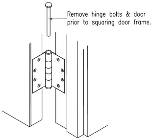
Step 2 Remove hinge bolts and door prior to squaring/leveling
door
frame. (Detail Q)
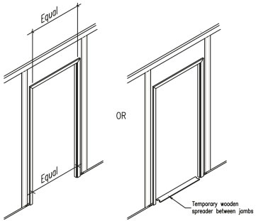
Step 3 Verify there is equal spacing between both jambs
by measuring or
by using a temporary wooden spreader. (Detail P)
|
|
 |
|
|
|
Detail
O
|
|
|
|
|
|
|
|
|
|
|
 |
|
|
|
|
|
|
|
|
|
|
|
|
|
|
|
 |
|
|
|
|
Detail
P
|
|
Detail
Q
|
|
|
|
|
|
|
|
|
|
|
|
|
Step
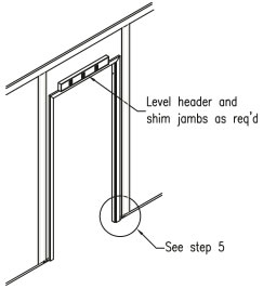
4
Level door header and shim jambs as required. (Detail R)
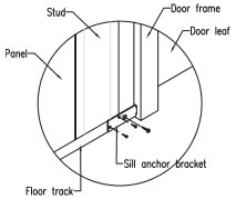
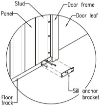
Step 5 Use the sill anchor brackets to anchor jambs
to the floor track.
(Detail S)
|
|
 |
|
|
|
|
 |
|
|
|
|
Installation
Note
|
|
|
|
|
|
|
|
|
|
|
|
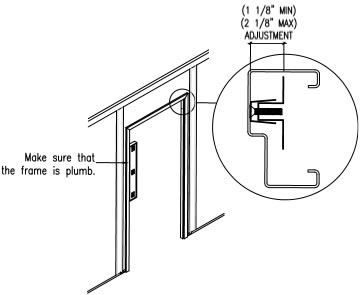
Make
sure that the frame is plumb. |
|
|
|
|
|
|
|
|
|
|
|
Step
6
Turn adjustment screw counterclockwise to secure frame.
Do not use these screws to plumb the frame. (Detail T) |
|
|
|
|
|
|
|
Detail
S
|
|
|
|
|
|
|
|
|
Detail
R
|
|
|
|
|
|
|
|
|
|
|
|
|
 |
|
|
|
|
|
|
|
|
|
|
|
|
|
|
|
|
|
|
 |
|
|
|
|
|
Detail
U
|
|
|
|
|
|
|
|
|
|
|
|
|
|
Step
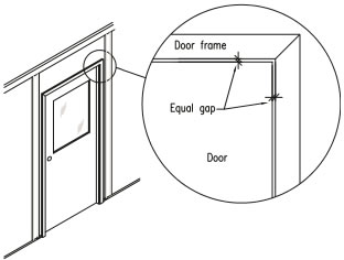
7
If the frame is installed properly, there will be an equal gap
between the door and the frame. (Detail U) |
|
|
Detail
T
|
|
|
|
|
|
|
|
|
|
|
|
|
|
|
|
Double
Door Installation
|
|
|
|
|
|
|
|
|
|
Walls
should be secure at this point. Check on this before installing
door.
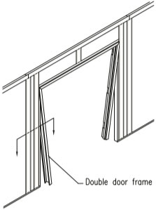
The double door assembly is shipped knocked down and is not
pre-hung in a panel. Framing for the door opening
includes steel tubes for 3" walls and steel channels for
1-9/16", 4-5/8" and 6" walls. The door should
be installed
during the wall installation. The steel assembly framing should
be in place with the remainder of the wall. All studs
should be secured to the cornice mold before adjusting the frame.
Note: The material sizes indicated in the
following steps are for a 6'-0" x 7'-0" double door
in an 8'-0" wall system. Sizes will vary for other door
sizes and
wall heights. Refer to drawings.
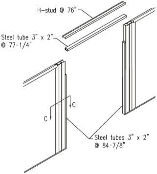
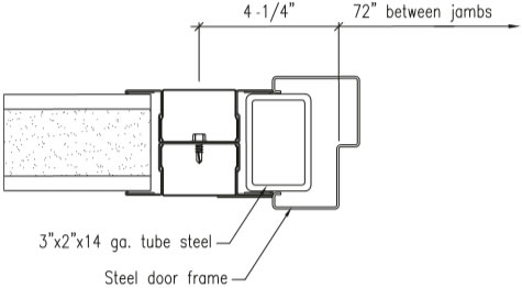
Assure that studs on each side of the door are plumb and located
properly according to the layout. The distance
between studs should be 76". (Detail V)
Install 84-7/8" vertical tubes or channels into each stud.
(Detail X) Note: Channels are installed with the
open side towards the stud. |
|
|
|
 |
|
 |
|
|
|
|
|
Detail
W
|
|
|
|
|
Detail
V
|
|
|
|
|
|
|
|
|
|
|
|
|
|
|
|
|
|
Set
77 1/4" tube or channel across opening to rest on vertical
supports. (Detail W) Place 76" H-stud on horizontal
tube or channel.
Install 37 1/8" x 12 7/8" header panels along with
the 12 1/8" header stud. Note that header stud will rest
on h-stud.
(Detail Y) |
|
|
|
|
|
|
|
|
|
|
 |
|
|
|
 |
|
|
|
|
Detail
X
|
|
|
|
|
|
|
|
|
|
|
|
Detail
Y
|
|
|
|
|
|
|
|
|
|
1)
Install cornice mold on top of wall, plumb studs and secure
studs to cornice mold.
2) Locate all frame parts before installing frame. Included
with the three (3) framing parts will be the following:
four (4) sill anchor brackets to be
installed at the bottom of the hinge jamb to secure the frame.
Six (6) 4-1/2" x
4-1/2" hinges, six (6) hinge
back-up plates to place between the hinge and door and four
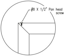
(4) #8x1/2" pan head
screws to secure frame header to jambs.
3) Install sill anchor brackets into the bottom of the hinge
jambs.
4) Install three (3) door frame parts into opening making
sure that the mitered joint connects properly.
(Detail 4 & 5) Plumb each
jamb and level header. Secure jambs at floor using sill anchor
brackets. (Detail 1)
Tighten adjustment screw to hold door
frame plumb. Install door frame header screws in top of frame
using
#8x1/2" pan head screws. (Detail
2)
5) Secure studs to tubes by fastening through the leg of the
studs and h-stud with #12-14 x 1-1/4" Tek 3 screws.
This must be done at the corners of
the frame and at 18" o.c. on both sides of the door.
(Detail 3)
6) Install hinge butts: one-half mounts to frame and the other
half to the door. Make sure the hinge back-up plates
are installed between the hinges and
the door.
|
|
|
7)
Once the wall is rigid, hang the door onto the frame by meeting
hinge butts together and replacing hinge
pins.
8) Operate door to check fit. Doors should swing easily.
9) Install head and foot bolts on inactive door |
|
|
|
|
|
|
|
|
 |
|
|
 |
|
|
|
|
|
|
|
 |
|
|
|
|
Detail
1
|
|
Detail
2
|
|
|
Detail
3
|
|
|
|
|
|
|
|
|
|
|
|
|
|
|
|
|
|
|
|
|
 |
|
|
|
 |
|
|
|
|
|
|
|
|
|
|
|
|
|
|
Detail
4
|
|
|
|
|
|
Detail
5
|
|
|
|
|
|
|
|
|
|
|
|
|
|
|
|
|
|
|
|
|
|
|
|
|
Dust
Cover Installation
|
|
|
|
|
|
|
|
|
|
|
|
|
|
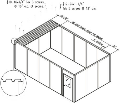
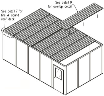
The
dust cover consists of metal decking and support beams, as required.
The standard decking is 22 gauge, 1-1/2"
type "B" deck, and is required to make the office
walls free-standing. The decking has a modified "V"
roll form
design. As such, it will grow or shrink in width during installation.
Care should be exercised to control the
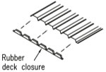
dimensions while installing. All Fire & Sound buildings
come with a rubber deck closure to fill the corrugation
openings between deck and building. |
|
|
|
|
|
|
|
|
|
|
|
|
|
 |
|
Note:
Unless the office has been specifically designed to have
a storage roof, it is not intended to hold the weight of a person
or storage. |
|
|
|
|
|
|
|
|
|
|
|
|
 |
|
|
|
|
|
|
Detail
7
|
|
|
|
|
|
|
|
|
|
|
|
|
|
|
|
 |
|
|
|
|
|
|
Detail
9
|
|
|
|
|
|
|
|
|
|
|
|
Detail
6
|
|
|
|
|
|
|
|
|
|
|
|
|
|
|
|
|
|
|
|
1)
Install the dust cover by placing the first piece of deck at
one end of the office, resting on the cornice mold.
Follow dust cover layout on building
plans. The edge without a return lip should be next to the outside
of the
building. (Detail 6)
2) Prior to screwing the dust cover down, insert the rubber
deck closure by tacking it between the dust cover and |
|
|
the
top of the cornice mold. (Detail 7) |
|
Detail
8
|
|
|
|
|
 |
|
|
3)
Secure decking to the cornice mold with #10-16 x
3/4" Tek 3 screws at 18" o.c.
along the seams and
with #12-24 x 1-1/4" Tek 5 screws
in every other
valley. (Detail 6)
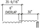
4) Make a mark on the cornice mold to locate the
placement of the next section of the
decking. This
dimension will vary between 35-3/8"
and 36-1/4".
5) Place the second piece of decking next to the first
piece with the edge overlapping the
return lip of the
first piece. Note: Be sure to
secure each piece.
6) Continue installing decking across the room as
instructed above to complete. (Detail
8) Overlapping
dust cover sections may be necessary.
(Detail 9)
Please refer to job drawings sent with
project. |
|
|
|
|
|
|
|
|
|
|
|
|
|
|
|
|
|
|
Non-Load
Bearing Beams
|
|
|
|
|
|
|
|
Place
support beams above the walls. Beams must be supported by
wall studs or steel columns at ends. Follow layout drawing
for proper beam placement.
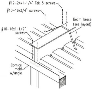
Step 1 Secure ends of beam with #10-16 x 1-1/2"
Tek 3 screws into cornice mold at wall. (Detail 10)
Step 2 Fasten roof deck to the beam with #12-14 x 1-1/4"
Tek 5 screws at 12" o.c. To complete the deck installation,
refer to dust cover installation on previous page.
Step 3 Attach conduit beam braces to the beam top flange
and dust cover.
|
|
|
 |
|
 |
|
|
|
Detail
11
|
|
|
|
|
|
|
|
Installation
Note
|
|
|
|
|
|
|
Detail
10
|
|
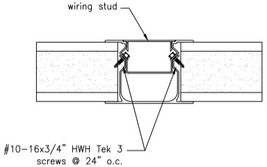
Electrical
wiring should be done by a qualified electrician. |
|
|
|
|
|
|
|
Electrical
|
|
|
|
|
|
 |
|
|
|
|
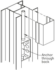
1)
Install handy boxes into studs at desired locations with a
#10-16 x 3/4"
Tek 3 screw. Fasten through the back
of the box (Detail 12) Typical
locations are 12"-18" above
the floor for duplex outlets and 48" to 54"
AFF for switches and single outlets.
2) Cut conduit as needed. Conduit should terminate just above
ceiling
level.
3) Install stud cover plates by cutting to size above and
below each handy
box location. Cover plates should
also terminate just above the ceiling
to allow for wiring across the ceiling.
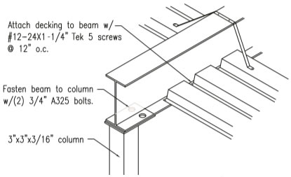
4) If installing a bean onto a column, follow steps 1-3 when
securing top
plate of columns. (Detail 11)
|
|
|
|
|
|
|
Detail
12
|
|
|
|
|
|
|
|
|
|
|
|
|
|
|
|
|
Acoustical
Ceiling Installation
|
|
|
|
|
|
|
|
|
|
Determine
the required finished ceiling height for the room. For ease
of installation and proper light fixture
clearance, the ceiling should be a minimum of 6" below
the underside of the deck (6-1/2" if an exhaust fan will
be
installed). Most building codes require a minimum clearance
of 7'-6" from the floor to ceiling.
1) Snap a chalk line 1" above the required ceiling height
around the perimeter of the room. This line should be
checked for level before snapping
the string. (Detail 14).
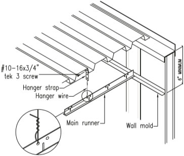
2) Cut wall mold as required and position so that top of angle
is even with the chalk line. Secure the wall angle to
studs and corners with #10-16x3/4"
tek 3 screws. Proceed around the room. Wall mold may be overlapped
or
miter cut at corner joints.
3) Mark the location of main runners by putting marks above
the wall mold. Tie a string around the wall mold and
stretch it across the room near the
position of the main runner. This will provide a reference
line to install hanger
straps and wires.
|
|
|
|
|
|
|
|
|
|
4) Attach wire hanger straps to the bottom of the dust
cover at 4' o.c. Along each main runner.
(Detail 15)
Make certain that a hanger wire is located
at each
corner where a lay-in light fixture
will be. Cut hanger
wire as needed, usually allowing an
additional 6" at
each end to twist in place. Install
wire through the
hanger strap; bending wire back down
and wrapping
tightly 3-4 twists. (Detail 16) |
|
|
|
|
|
|
 |
|
|
 |
|
|
|
|
|
|
|
|
|
|
|
|
Detail
16
|
Detail
15
|
|
|
|
|
|
|
|
|
Detail
14
|
|
|
|
|
|
|
|
|
|
|
|
|
|
The
ceiling grid consists of two major components, 12' main runners
and 4' cross tees. (Detail 17) The main
runners typically run the longer length of the room. Closely
follow the layout drawing provided to assure easy
installation and proper material quantities.
5) Install 12' main runners at locations shown on drawing using
hanger wire provided. Be certain that 4' cross tee
anchor points correspond to the ceiling
plan. Allow the main runner to fully rest on the wall mold.
6) The ceiling wire may then be attached to the main runner.
Be sure to wrap the wire around itself at least 3 times.
(Detail 16) Care should be taken
to install the main runner straight and level. Continue until
all main runners are
installed.
7) Install cross tees at points indicated on the drawings by
inserting tabs into anchor points. Trim pieces at wall, as
required, for tee to rest fully on
wall mold. To strengthen the grid the tees may be secured to
the wall mold with
pop-rivets (not supplied). Intersections
of cross tees and main runner must form a 90-degree corner.
(Detail 18)
8) Place light fixtures into grid at locations indicated on
drawing. Make certain that a hanger wire is located at each
corner where a lay-in light fixture
will be.
9) Cutting ceiling panels may be accomplished with the panels
facing up using a saw or a very sharp fiberboard
knife. Measure and cut each of the border
panels individually.
10) Lay-in panels are installed by carefully tilting the panel
to fit through grid opening then resting the panel on
cross tee and main runner flanges. Exercise
care when handling ceiling panels to avoid marring the surface.
Handle edges of panels, keeping fingers
off the finished side of the panel as much as possible. Clean
hands are
necessary for a clean job. It may be
necessary to use the left over portion of the tile for other
cut pieces. |
|
|
|
|
 |
|
|
 |
|
|
|
|
|
|
|
Detail
17
|
|
|
|
|
|
|
|
|
|
Detail
18
|
|
|
|
|
|
|
|
In-Plant
Office Fastener Guide
|
|
|
|
Part
No.
Size
|
Sample
Image
|
Description,
Uses & Quantities
|
|
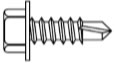
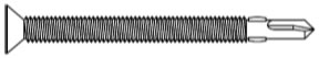
FAS87630
#10-16x3/4"
|
 |
Hex
Washer Head Tek 3
• Assemble studs (8 per 8', 10 per 9', 12 per
10', etc.)
• Secure studs, corners and wall starter to
floor track and cornice mold (3 per
stud)
• Fasten roof deck at seams (18" o/c at
seams)
• Fasten beam braces to deck (2 per brace)
• Fasten ceiling hanger straps to deck (1 per
strap) |
|
FAS35790
1/4"-20x7/8"
|
 |
Phillips
Flat Head
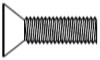
• Assemble 3" corner post (4 for 8', 5 for 9',
6 for 10', etc.) |
|
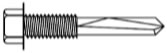
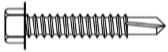
FAS10-16CRIMP
#10-16x3/4"
|
 |
Hex
Head Type 1 Crimptite Tek 2
• Assemble studs (8 per 8', 9 per 9', etc.) |
|
FAS87780
#10-16x1 1/2"
|
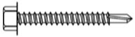 |
Hex
Washer Head Tek 3
• Fasten beams to cornice mold (4 per recessed
beam plate, 2 per beam saddle,
4 per non-load bearing beam) |
|
FAS87845
#12-24x1 1/4"
|
 |
Hex
Washer Head Tek 5
• Fasten roof deck to beams (12" o/c at
beam)
• Fasten beam braces to beams (2 per brace)
• Fasten roof deck to cornice mold (12" o/c
at deck ends) |
|
FAS87849
#12-24x2 1/2"
|
 |
Phillips
Flat Head Tek 3
• Fasten wood support boards to cornice
mold (2 per board) |
|
FAS87840
#12-14x1 1/4"
|
 |
Hex
Washer Head Tek 3
• Fasten shear panels (12" o/c all around
shear panel and 8 per bracket)
• Fasten studs to double door tubes (30 per
door) |
|
FASDWS08108
#8 x 1 1/2"
|
 |
Phillips
Bugle Head Drywall Screw
• Fasten 3/4" plywood/OSB to roof deck
(45 per sheet) |
|
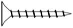
FAS87580
#10-16x5/8"
|
 |
Phillips
Pan Head Tek 3
• Fasten vinyl base to wall (7 per pc. of
vinyl base and 2 per corner) |
|
FAS166310
|
|
HVAC
Screw Packet
• 1 Pkg/per Unit |
|
|
|
|
|
|
Cleaning
& Maintenance Protocol: Modular Wall Systems
|
|
|
|
|
|
Wipe
the panels, studs and extrusions with an owner approved alcohol
wipe or mild soap and water with a damp
sponge or rag. If any chemicals are to be utilized, spot check
with extra materials or in an inconspicuous place
prior to use to insure that the finish of the wall system
is not damaged.
Upon request, we can provide touchup paint, vinyl facings
and replacement material based on your requirements.
|
|
|
|
|
|
Aluminum
Wall System
|
|
|
|
|
|
|
|
|
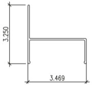
The
aluminum version installs in the same manner as the modular
office system.
|
|
|
|
|
|
|
|
|
|
|
 |
|
|
|
|
|
|
|
|
|
|
Standard
Quick-Ship Modular Offices, Modular Offices, Inplant Building,
Inplant Buildings, Inplant Modular Office, Inplant
Modular Offices, Inplant Office, Inplant Offices, Partition
Wall Systems, Prefab Office, Prefab Offices, Inplant Modular
Offices,
and Prefabricated Offices from your complete source for material
handling equipment.
|
Back
to Product Category |
 |
|