
 |
ENGINEERED
STEEL PRODUCTS |
| Priced
Full Line Products Catalog |
20
Technology Way • West Greenwich, RI 02817
Toll free:(800) 421-0314 • In RI:(401) 272-4570 • Fax:(401)
421-5679 |
|
|
|
|
Back
to Product Category
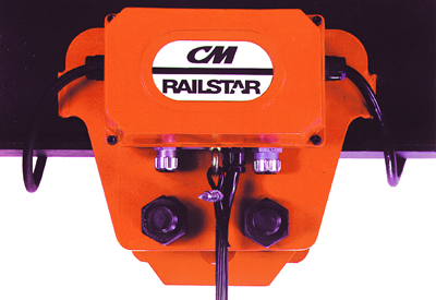
Railstar Motor Driven
Trolley
|
|
|
|
|
|
|
|
•
Fits wide range of beam sizes for max versatility
• For use with hook suspended single speed hoists
that are equipped with reversing contactor
• Steel plate side frames
• Steel spur gearing for optimum strength and
smooth operation
• Durable hardened cast iron trackwheels that
operate on standard S-beams or flat flanged
beams
• Lifetime lubricated double row ball bearings for
high efficiency, low maintenance
• Cast iron control enclosure
• Four-button control station included for
operating single speed hoist proportioned
to 20 ft. lift
• Trolley guards standard
• 115 volt control circuit
• One-year warranty
• Imported |
|
 |
|
|
|
|
|
 |
|
|
|
|
|
Railstar
Motor Driven Trolley Dimensions (inches) |
|
|
| Dimension |
Rated
Capacity* |
| 1/8
- 2 Tons |
3
Tons |
| Min. radius
curve |
52 |
71 |
| Beam range |
S6x12.5-S18x54.7 |
S8x18.4-S24x79.9 |
| A |
12 3/4 |
14 1/8 |
| B |
6 3/8 |
6 3/4 |
| C** |
4 13/16 |
5 1/4 |
| D |
3 9/16 |
3 15/16 |
| E |
2 9/16 |
2 15/16 |
| F** |
4 3/4 |
5 3/16 |
| G** |
6 |
6 5/16 |
| H** |
17 ft. |
17 ft. |
| J |
7 1/2 |
9 5/16 |
| K |
4 1/8 |
4 11/16 |
| SINGLE PHASE
L |
12 3/4 |
15 3/16 |
| THREE PHASE
L |
11 7/16 |
13 7/8 |
| M** |
1 1/2 |
2 15/16 |
| N** |
3/8 |
3/4 |
| P** |
1 7/16 |
1 9/16 |
| Q** |
5 1/8 |
5 7/8 |
| R |
1/2 |
3/4 |
| S |
1 1/16 |
1 1/16 |
| T** |
8 7/8 |
9 9/16 |
|
|
|
**Dimensions given
are for minimum S-beam and will vary with larger beams. |
|
|
|
Railstar
Motor Driven Trolley Specifications |
|
|
Rated
Cap*
(tons) |
Product
Code |
Operating
Voltage |
Phase |
Travel
Speed |
Motor
HP |
Min
Beam
Size |
Max
Beam
Size |
Shipping
Weight |
50 hertz
(FPM) |
60 hertz
(FPM) |
| 50 hertz |
60 hertz |
| 1/8-2 |
0300 |
220/380-415 |
220-240/440-480 |
3 |
65 |
78 |
1/3 |
S6x12.5 |
S18x54.7 |
108 lbs |
| 1/8-2 |
0301 |
n/a |
110-120 |
1 |
n/a |
78 |
1/3 |
S6x12.5 |
S18x54.7 |
113 lbs |
| 3 |
0302 |
220/380-415 |
220-240/440-480 |
3 |
65 |
78 |
3/4 |
S8x18.4 |
S24x79.9 |
185 lbs |
| 3 |
0303 |
n/a |
110-120 |
1 |
n/a |
78 |
3/4 |
S8x18.4 |
S24x79.9 |
190 lbs |
|
|
|
Note:Three
phase units are reconnectable for high and low range voltage. |
|
|
|
 |
|
Order
Online, by Phone, or by E-Mail |
|
|
|
~
Add items to your online shopping cart ~
Click the Model No. of the item you wish
to purchase. |
|
|
|
Railstar
Motor Driven Trolley Prices |
|
|
Product
Code |
Capacity |
Travel
speed (FPM) |
Standard
Beam Height |
Standard
Flange Width |
Price |
|
1/8
- 2 tons |
78 |
6
- 18" |
3
3/8 - 6" |
$3,578 |
|
1/8
- 2 tons |
78 |
6
- 18" |
3
3/8 - 6" |
$3,578 |
|
3
tons |
78 |
6
- 18" |
4
- 7" |
$4,232 |
|
3
tons |
78 |
8
- 24" |
4
- 7" |
$4,232 |
|
|
|
Universal hook plate
and 4 button single speed control station included.
Standard P.B. drop is 16 ft. Standard Power Cord length is 4 ft. imported. |
|
|
Railstar
Motor Driven Trolley Installation |
|
|
|
|
|
|
|
|
| UNPACKING
INFORMATION |
|
|
|
 |
|
After
removing the trolley from the shipping carton,
carefully inspect the external condition of the cords,
control box, gear reducer and motor for damage that
may have occurred during shipment and handling.
Check to make sure all parts (trolley side frame
assembly with control box, trolley side frame with
gear reducer and motor, hook plate, suspension bolts,
spacer washer, spacer tubes, lockwashers and nuts)
are furnished. Also, before attempting to install the
trolley, make sure that the power supply indicated
on the nameplate is the same as the power supply
on which the unit is to operate. If there is damage,
refer to packing slip envelope for claim procedure. |
|
|
|
|
|
|
|
|
|
|
Due
to the variations in beam flange widths, it is
suggested that the beam flange width be measured to
determine the exact distribution of spacer washers. The
distance between trackwheel flanges (dimension "X")
should be 1/8 to 3/16 inch (3.2 to 4.8 mm) greater than
the beam flange width for straight runway beams, and
3/16 to 1/4 inch (4.8 to 6.3 mm) greater than the beam
flange width if runway system includes sharp curves.
The use of other than our supplied washers may result
in trackwheel to beam flange variations and thus Table
2 will not apply. |
|
|
|
|
| INSTALLATION |
|
The
hoist, trolley and hook suspension for suspending
the hoist from the trolley may be packed separately. If
necessary, assemble the hook suspension to the hoist
according to the instruction furnished with the suspension
and/or the instruction in the manual furnished with the
hoist. |
|
|
|
|
|
|
|
|
|
|
|
|
|
The
Railstar Motor Driven Trolley is designed for
operation at ambient temperatures of 0° to 100°F
(-17 to 38°C). |
|
|
|
|
|
|
Now
install the trolley on the beam by sliding one side
frame out far enough to allow the trackwheels to clear
the beam flange Lift the trolley up so that the track-
wheels are riding on the beam. Draw the side frames
together and tighten the nuts snugly to compress the
lockwashers. Suspend the hoist from the trolley hook
plate so that the hoist power and control cords are son
the control box side of the trolley. Verify distance
between trackwheel flanges (dimension "X") as noted
above. |
|
|
|
|
|
 |
|
|
|
|
|
|
|
|
|
|
|
|
|
|
|
|
|
The
stops must be positioned so as to not exert impact force on the hoist frame
or trolley wheels. They must contact
the ends of the trolley side frames. |
| TROLLEY
TO BEAM |
|
|
|
It
is recommended that the trolley be mounted on the beam prior to suspending
the hoist from the trolley. Before
attempting to mount the trolley on the beam, measure the actual width of
the beam flange on which the trolley is to
operate. Using this measurement determine the arrangement of the spacer
washers using Figure 1 and Table 2. Chart
A of Table 2 shows the washer arrangement for the 1/8-2 ton (250-2000 kg.)
trolley, while Chart B provides data
for the 3 ton (3000 kg.) trolley. Loosely assemble the side frames, hook
plate, spacer washers, spacer tubes, lock-
washers and nuts on the suspension bolts as shown in Figure 1. |
|
|
|
|
|
|
|
|
TABLE
1 |
|
|
 |
|
CHART
A: 1/8 THRU 2 TON RAILSTAR TROLLEY
WASHER SPACING |
|
|
|
| FLANGE
WIDTH |
NUMBER
OF SPACER WASHERS |
| IN. |
MM |
A |
B |
C |
D |
| 31/4 |
82.5 |
22 |
0 |
0 |
0 |
| 33/8 |
85.7 |
21 |
1 |
0 |
0 |
| 35/8 |
92.1 |
19 |
2 |
1 |
0 |
| 4 |
101.6 |
16 |
3 |
3 |
0 |
| 41/8 |
104.8 |
15 |
4 |
3 |
0 |
| 45/8 |
117.5 |
11 |
6 |
5 |
0 |
| 5 |
127 |
8 |
7 |
7 |
0 |
| 51/8 |
130.2 |
7 |
8 |
7 |
0 |
| 51/4 |
133.3 |
6 |
8 |
8 |
0 |
| 51/2 |
139.7 |
4 |
9 |
9 |
0 |
| 55/8 |
142.9 |
3 |
10 |
9 |
0 |
| 6 |
152.4 |
0 |
11 |
11 |
0 |
|
|
|
|
|
|
|
Electrical
Connections |
|
|
|
The trolley
electrical connections must be completed as
shown in Figure 2 (see below). The hoist and trolley must
be supplied with adequate electrical power in order to
operate properly. For proper operation, the voltage,
(measured at the trolley terminal board with the hoist
operating in the up direction with full load) must be
as indicated in the table below. |
|
|
|
|
|
|
|
| TABLE
2 |
|
|
|
| CHART
B: 3 TON (3000 Kg) |
|
NOMINAL
CURRENT |
MIN. RUNNING
VOLTAGE |
MIN. STARTING
VOLTAGE |
| 115-1-60 |
104 |
98 |
| 230-3-60 |
198 |
198 |
| 460-3-60 |
396 |
396 |
| 220-3-50 |
198 |
198 |
| 380-3-50 |
352 |
352 |
| 415-3-50 |
374 |
374 |
|
|
FLANGE
WIDTH |
NUMBER
OF SPACER WASHERS |
| IN. |
MM |
A |
B |
C |
D |
| 4 |
101.6 |
24 |
0 |
0 |
0 |
| 41/8 |
104.8 |
23 |
1 |
0 |
0 |
| 45/8 |
117.5 |
19 |
3 |
2 |
0 |
| 5 |
127 |
16 |
4 |
4 |
0 |
| 51/8 |
130.2 |
15 |
5 |
4 |
0 |
| 51/4 |
133.3 |
14 |
5 |
5 |
0 |
| 51/2 |
139.7 |
12 |
6 |
6 |
0 |
| 55/8 |
142.9 |
11 |
7 |
6 |
0 |
| 6 |
152.4 |
8 |
8 |
8 |
0 |
| 61/4 |
158.7 |
6 |
9 |
9 |
0 |
| 63/8 |
161.9 |
5 |
10 |
9 |
0 |
| 7 |
177.8 |
0 |
12 |
12 |
0 |
|
|
|
|
|
|
|
Signs of inadequate
electrical power (Low Voltage) are: |
|
|
•
Noisy hoist or trolley operations due to brake and/or
contactor chattering.
• Dimming of lights or slowing of motors connected
to the same circuit.
• Heating of the hoist and/or trolley motors and other
internal components as well as heating of the wires
and connectors in the circuit feeding the unit.
• Failure of the hoist to lift the load due to motor stalling.
• Blowing of fuses or tripping of circuit breakers. |
|
|
|
|
|
|
|
|
 |
|
To
avoid these low voltage problems, the trolley must
be connected to an electrical power supply system that
complies with the National Electrical Code and
applicable local codes. This system must also be rated
for a minimum of 20 amps and it must have #14 AWG
or larger wiring, a disconnecting means, overcurrent
protection (slow blow fuses or inverse-time type
circuit breakers) and provisions for grounding. |
|
|
|
|
|
|
|
|
|
|
|
|
|
|
|
|
 |
|
|
| TYPICAL
POWER SUPPLY SYSTEM |
|
|
|
|
|
If
grounding is to be through the metal to metal contact
between trackwheels and the operating flange of the
beam, make sure that: |
|
|
|
|
|
|
|
1.
No paint or other insulating material is applied to the
operating flange of the beam.
2. No paint or other insulating material is applied to the
trackwheel treads. |
|
|
|
|
|
|
|
|
|
|
|
|
|
|
|
|
|
|
|
|
|
|
|
Remember,
operation with low voltage can void our
repair/replacement policy. When in doubt about any
of the electrical requirements, consult a qualified
electrician. Always disconnect the power from the
power supply system and lockout/tagout
disconnecting means before servicing the trolley or
hoist. |
|
|
|
|
|
|
|
 |
|
|
|
|
|
|
|
|
|
|
|
|
|
|
|
|
|
|
|
|
|
|
|
|
 |
|
|
|
|
|
|
|
|
|
|
|
|
|
|
3.
The trolley beam is permanently grounded to the
building ground system. |
|
|
|
|
|
|
|
|
4.
The hoist power cord, trolley power cord, hoist
control cord, and the trolley control cord are
grounded to the control box (see figures 3 and
4 below). |
|
|
|
|
|
|
|
|
|
|
|
|
|
|
|
|
|
|
|
|
|
|
|
|
|
|
|
|
|
|
|
|
|
LENGTH OF
EXTENSION
CORD |
SINGLE PHASE |
THREE PHASE |
MINIMUM
WIRE SIZE |
MINIMUM
WIRE SIZE |
| UP TO 50 FEET
(15.2 M) |
#14AWG |
#16AWG |
| 80 FEET (24.4
M) |
#12 AWG |
#16AWG |
| 120 FEET (36.6
M) |
#10 AWG |
#14 AWG |
|
|
 |
|
|
|
|
|
|
|
|
|
|
|
Low
voltage can also be caused by using an undersize
extension cord to supply power to the trolley. The
following chart should be used to determine the size
wires in the extension cord in order to minimize the
voltage drop between the power source and the
trolley control box. |
|
|
|
|
|
|
|
|
|
|
|
|
|
|
|
|
|
|
|
|
|
The
following wiring diagrams show connections to be
made within trolley control box. For special units, see
wiring diagram supplied with unit. Note: Trolley power
cord must be replaced (if necessary), hoist power cord
must be connected to the trolley power circuit, hoist
control cord must be connected to the trolley and wired
to the trolley control cord and the control cord must be
shortened (if necessary) before the system supplying
power to the trolley is energized. |
|
|
|
In
addition, as shipped from the manufacurer, the three
phase trolleys are connected to operate on 380-415
Volts, 3 Phase, 50 Hertz or 440-480 Volts, 3 Phase,
60 Hertz. These units can be converted to operate on
220 Volts, 3 Phase, 50 Hertz or 230 Volts, 3 Phase,
60 Hertz. To do this, reconnect the motor leads to the
motor cord and move lead #10 at the transformer
terminal board to the "220" position as shown on the
wiring diagram supplied with the trolley or wiring
diagram 03702. Be sure to remark, using tape or
some other suitable material, the trolley identification
plate to indicate that the unit is suitable for operation
on 220-3-50 or 230-3-60. |
|
|
|
|
|
|
|
| CONTROL
STATION |
|
|
|
|
The
standard trolleys are supplied with a four button
control station. The hoist control buttons are the single
speed type that can be used to control a single speed
hoist that is equipped with a reversing contactor. The
trolley control buttons are also the single speed type. |
|
|
|
|
|
|
|
|
|
|
|
To
shorten the cord, measure the distance the control
station is to be raised. Remove the cover from the control
station and disconnect the wires from the various terminals.
Using wire cutters, cut the external wire rope strain relief
just above the fitting used to form the loop. Measuring
from the end of the longest wire, cutoff the cord the
distance the station is to be raised. Using the cut-off piece
of cord as an example, remove the outer jacket and
prepare the individual wires of the shortened cord
accordingly. |
Unless
ordered special, the control station is suspended
from the trolley control box by a cord that is
approximately 16'-3" (4.95 M) long. If this is too long
for your application, the cord should be shortened so
that the control station is approximately four feet above
the operating floor. |
|
|
|
|
|
|
|
|
|
|
|
|
|
|
|
|
|
|
|
|
|
Slide
the prepared cord through the grommet on top
of the control station. Clamp the cord to the top of the
control station and, using the wiring diagram supplied
with the trolley, connect the wires to the various terminals.
Now, remove the insulation from the wire rope stain relief.
Slide the clamp sleeve (from the wiring kit) up on the
wire rope and feed the rope around the pin at the top
of the station. Feed the end of the wire rope through the
other side of the clamp sleeve. Pull on the end of the wire
rope until it supports the control station. Slide the clamp
sleeve down to form a tight loop and then squeeze the
clamp sleeve using a vise or very large pliers to secure
the loop. Reattach the cover to the control station. |
|
 |
|
|
|
|
|
|
|
|
|
|
|
|
|
|
|
|
|
|
| TROLLEY
POWER CORD |
The
short power cord furnished is for use with a collector and bus system. It
should be discarded if a cable is to supply
power to the trolley. Connect the "new" power cord to the terminal
board as shown in Figure 3. The box connector
must be made tight on the cable, and if necessary, a separate strain relief
should be provided to prevent any stress on
the wires of the power cord. |
|
|
|
|
|
|
|
|
 |
|
FIGURE
3. HOIST POWER CORDS CONNECTIONS
(other wiring is not shown for clarity) |
|
|
|
| HOIST
CONTROL CORD |
Energize the power
supply system. Depress the trolley
control button. If the movement of the trolley does not
agree with the direction arrows on the control station, de-energize the
power supply system. Remove trolley control
box cover and interchange the red and black wires as
shown in Figure 5. |
The
hoist control cord must be shortened and run into
the trolley control box so that the hoist can be controlled
from the four button control station suspended from the
trolley. To do this, form a loop in the hoist control cord
as shown in figure 2. Allowing 5 to 6 inches (127.0 to
152.4 mm) for making connections inside the control
box, cut-off the hoist control cord. The hoist control
station and excess cord can be discarded. Strip 5" to
6" (127.0 to 152.4 mm) of the outer jacket from the
cord to expose the individual wires. Run the cord
through the box connector and firmly tighten the outer
nut of the connector to secure the cord. Strip .3"
(9.5 mm) of insulation from the individual wires.
*Connect the brown, yellow and blue wires to the
terminal board as shown in Figure 4. Loosen one of
the screws used to attach the terminal board or trans-
former to the control box. Firmly crimp a spade type
terminal (from the wiring kit) to the end of the green
wire and slide the terminal under the head of the screw.
Firmly tighten screw to insure proper ground. |
|
|
|
|
|
|
|
|
|
Now, depress
the "up" button. If the hoist hook lowers,
deenergize the power supply system and interchange the
red and black wires of the hoist power cord at the terminal
board as shown in Figure 5. |
|
|
|
|
|
|
|
 |
|
|
|
|
 |
|
|
|
|
|
|
|
|
THREE-PHASE
UNITS |
|
|
A
three phase motor can rotate in either direction
depending on its connection to the power supply.
Therefore, the direction of trolley and hook travel
relative to the selected indicated direction must be
checked before the trolley is put into service. If the
hoist power cord is not properly connected to the
terminal board inside the trolley control box, serious
damage could result and the hoist limit switches are
ineffective. The trolley should be checked first and
then the hoist. |
(OTHER
WIRING IS NOT SHOWN FOR CLARITY) |
|
|
|
|
|
|
|
*Color
coding of wires may vary. Refer to wiring diagram supplied with hoist for
color coding of up, down
and common wires. |
|
Hoist Trolley, Trolleys,
CM Railstar Motor Driven Trolley, Wide Range of Beam Sizes, Use with Hook
Suspended
Single Speed Hoists, and Trolley Guards from your source for material
handling equipment. |
Back
to Product Category |
 |
|