 |
ENGINEERED
STEEL PRODUCTS |
| Priced
Full Line Products Catalog |
20
Technology Way • West Greenwich, RI 02817
Toll free:(800) 421-0314 • In RI:(401) 272-4570 • Fax:(401)
421-5679 |
|
|
|
|
Back to Product Category
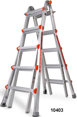
LITTLE
GIANT 375 LADDER SYSTEMS
SUPER DUTY TYPE 1AA
|
|
|
|
|
|
|
|
|
|
|
|
|
|
|
|
|
|
 |
|
|
|
 |
|
 |
|
|
|
|
|
|
|
|
|
|
|
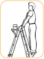
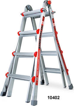
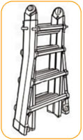
For heavy-duty jobs, nothing
beats the Super Duty
Type 1AA Little Giant Ladder.
When you need industrial-strength,
only one ladder will
do—the Little Giant Type 1AA. It’s government rated
to a whopping 375 pounds, so you know it can stand up
to even the most demanding applications.
And because it’s a Little
Giant, the Type 1AA gives you
the advantages of traditional A-frame ladders, extension
ladders, stepladders and even scaffolding—all in one
convenient package. |
|
Safety
The Little Giant is designed to be the safest ladder on
the planet. Since it’s adjustable, the Little Giant can
be used safely on stairs, ramps, curbs, docks or other
uneven surfaces. |
|
|
|
|
|
|
Strength
The Little Giant is made of heavy-wall, 6005-T5
aluminum—the very same material used in aerospace
construction. So it’s ultra-strong while remaining light
and portable.
In fact, The Little Giant Type 1AA is government-rated
to hold up to 375 pounds, but has survived brutal stress
testing of up to 1200 pounds with absolutely no
structural failure. |
|
|
|
|
|
|
Little
Giant Type 1AA Features:
* Heavy-wall aircraft-grade
aluminum construction
* Rated to hold up to 375 lbs.
* Combines 24 different ladders into on convenient system
* Lightweight and portable
* Complies with all applicable OSHA ANSI A14.2
standards
* Includes a full Lifetime Warranty |
|
|
|
|
|
|
Versatility
No other ladder gives you the versatility of a Little
Giant. Independent tests prove the Little Giant will
replace 60-70% of all portable ladders currently being
manufactured.
When you buy a Little Giant, you’re not just getting one
ladder. You’re getting 24 different ladders combined to
make the world’s most versatile ladder system. |
|
|
|
|
|
|
|
|
|
|
|
|
|
|
Little Giant Ladder
Configurations: |
|
|
|
|
|
 |
|
|
|
|
|
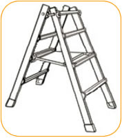
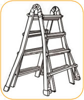
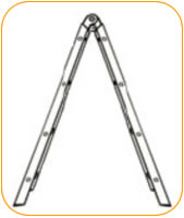
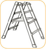
A-Frame Ladder
With a simple click of the patented hinge, the Little Giant can be used
as a
traditional A-Frame ladder. |
|
|
|
|
|
|
|
|
|
 |
A-Frame
Ladder |
|
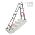
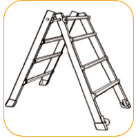
Staircase
Ladder
Because it's adjustable in one-foot increments, the Little Giant allows
one side
of the ladder to be extended allowing safe use on uneven surfaces like
staircases,
curbs or docks. |
|
|
|
|
 |
|
|
|
|
|
|
Staircase
Ladder |
|
90°
Ladder
Traditional ladders make working close to walls nearly impossible. With
the Little
Giant, one adjustment allows you to safely work against any vertical surface. |
|
|
|
|
 |
90°
Ladder |
|
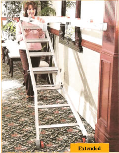
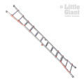
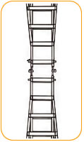
Extension
Ladder
For large projects the Little Giant easily converts to a stable extension
ladder allowing you to reach rooftops, tree limbs and more with ease. |
|
|
|
|
 |
|
|
|
|
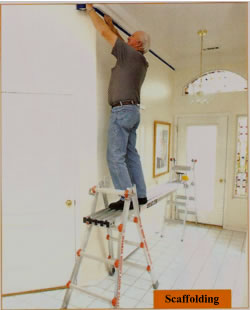
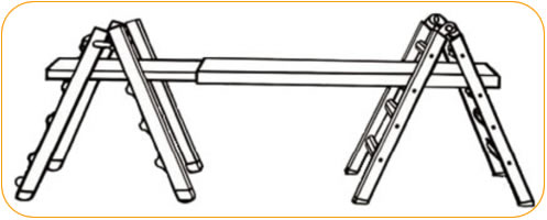
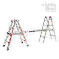
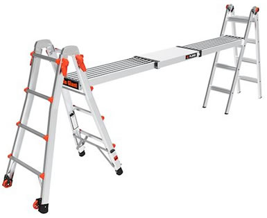
Scaffolding
Since the Little Giant pulls apart to form two scaffold trestles, you just
add the Little Giant work plank (sold separately) to form a convenient scaffolding
system. |
|
Extension
Ladder |
|
|
|
|
|
|
|
Scaffolding |
|
|
|
|
|
|
|
|
|
Specifications
- 375 lbs. Rated - Lifetime Warranty |
| Part # |
Model No. |
Stepladder
Height |
Extension
Height |
Scaffolding
Height |
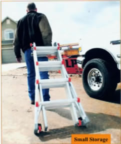
Storage
Height |
Weight
Capacity |
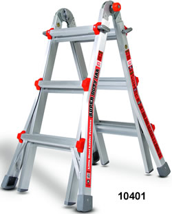
| 10401 |
M13 |
3'-5' |
7'-11' |
3' |
3' 7" |
375 lbs |
| 10402 |
M17 |
4'-7' |
9'-15' |
4' |
4' 7" |
375 lbs |
| 10403 |
M22 |
5'-9' |
11'-19' |
5' |
5' 7" |
375 lbs |
|
|
|
 |
|
Order
Online, by Phone, or by E-Mail |
|
|
|
~ Add
items to your online shopping cart ~
Click a Part No. of the item you wish to
purchase. |
|
|
PRICES
FOR 375 LADDERS |
| Part No. |
Description |
Weight |
Prices |
| 10401 |
13' |
36 lbs |
$548.33 |
| 10402 |
17' |
45 lbs |
$600.00 |
| 10403 |
22' |
54 lbs |
$676.67 |
|
|
|
|
|
|
|
|
|
|
|
|
Accessories |
|
|
|
|
|
|
|
|
|
|
|
|
 |
|
|
 |
|
 |
|
|
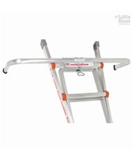
WingSpan
Ladder
Stand Off
Model No. - 10111 |
|
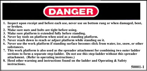
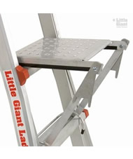
Work Platform
Model No. - 10104
300 lbs Rated |
|
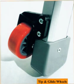
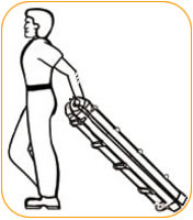
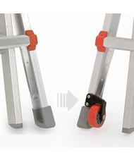
Tip &
Glide Wheel Kit
Model No. - 10940 |
|
|
 |
|
|
 |
|
Ladder
Plank (250 lbs Rated)
Model No. - 11069 - 9' (6' to 9')
Model No. - 11813 - 13' (8' to 13')
Model No. - 11915 - 15' (9' to 15') |
|
|
Ladder Rack
Model No. - 15097
75 lbs Rated |
|
|
 |
|
 |
|
 |
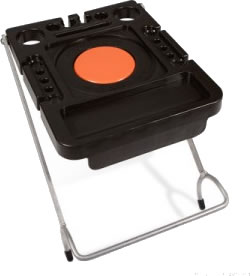
Project
Tray
Model No. - 15012 |
|
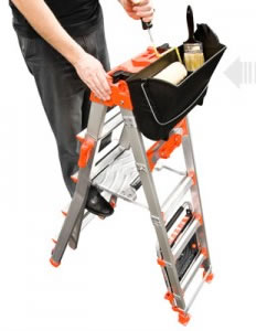
Cargo
Hold
Model No. - 15040-001 |
|
Fuel
Tank
Model No. - 15050-001 |
|
|
|
|
Order
Online, by Phone, or by E-Mail |
|
|
|
~ Add
items to your online shopping cart ~
Click a Part No. of the item you wish to
purchase. |
|
|
PRICES
FOR ACCESSORIES |
Part
No. |
Description |
Weight
(lbs) |
Prices |
|
Work
Platform |
8 |
$53.33 |
|
WingSpan
Ladder StandOff |
10 |
$61.67 |
|
Tip
& Glide Wheel Kit |
2 |
$33.33 |
|
Ladder
Rack |
8 |
$33.33 |
|
6'
- 9' Adjustable Plank |
35 |
$308.33 |
|
8'
- 13' Adjustable Plank |
48 |
$376.67 |
|
9'
- 15' Adjustable Plank |
59 |
$440.00 |
|
Project
Tray |
- |
$46.67 |
|
Cargo
Hold |
- |
$25.00 |
|
Fuel
Tank |
- |
$40.00 |
|
|
|
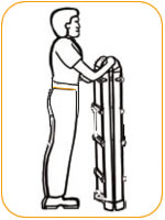
Operating
Instructions for Little Giant Ladder System® |
|
|
|
|
|
|
|
|
|
|
|
|
|
|
|
|
|
|
|
|
|
|
|
|
|
|
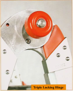
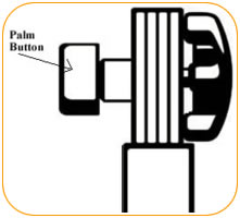
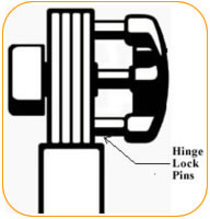
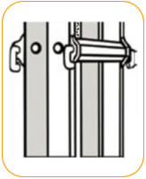
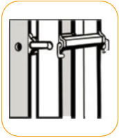
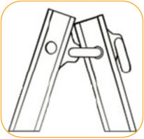
A. The Hinge - located
at the top of the ladder when it is in storage position, permits you to
alter the shape of the ladder.
The hinge locks in the following positions (See Figures A-1, A-2, and
A-3). |
|
|
|
|
|
|
|
|
|
|
|
|
|
|
|
|
|
|
|
|
|
|
|
|
|
|
|
 |
|
|
|
|
|
 |
|
|
|
|
 |
|
|
|
|
|
|
|
Figure
A-1 |
|
|
|
|
|
Figure
A-2 |
|
|
|
|
Figure
A-3 |
|
|
|
|
|
|
|
|
|
|
|
|
|
|
|
|
|
|
|
|
|
|
|
|
|
|
|
|
|
|
|
1. Unlock the hinge by pushing
straight in on the Palm Button until it stays in the open (unlocked) position
on both
hinges (See Figures A-4 and A-5). |
|
|
|
|
|
|
|
|
|
|
|
|
|
|
|
|
|
|
|
|
|
|
|
|
|
 |
|
|
 |
|
|
|
|
 |
|
|
|
Figure
A-4
LOCKED |
|
|
Figure
A-5
UNLOCKED |
|
|
|
|
Hinge |
|
|
|
|
|
|
|
|
|
|
|
|
|
|
|
|
|
|
|
|
|
|
|
|
|
|
|
|
|
|
|
a.
NOTE - If there is pressure on hinge lock pins it will be difficult to unlock
the hinge. To relieve pressure,
simply adjust one half of the ladder back and forth until hinge lock pins
move without force. |
|
|
|
|
|
|
|
|
|
|
|
|
|
|
|
|
|
|
|
|
|
|
|
|
|
|
|
|
b.
NOTE - DO NOT FORCE HINGE LOCK in or out with any tools as it will cause
permanent damage to
the hinge mechanism. It should never require more than light pressure to
unlock the hinge if the holes are
properly aligned. |
|
|
|
|
|
|
|
|
|
|
|
|
|
|
|
|
|
|
|
|
|
|
|
|
|
|
2.
You may now open the ladder to the A-frame position by pulling the two ladder
halves apart until both hinge lock
pins snap into the A-frame locked position. |
|
|
|
|
|
|
|
|
|
|
|
|
|
|
|
|
|
|
|
|
|
|
|
|
|
|
3.
Now place the ladder into the extension position by again pushing straight
in on the palm buttons of both hinges
(See Figures A-4 and A-5). |
|
|
|
|
|
|
|
|
|
|
|
|
|
|
|
|
|
|
|
|
|
|
|
|
|
|
Rotate
either side of the ladder until the hinge locks snap into their locked position. |
|
|
|
|
|
|
|
|
|
|
|
|
|
|
|
|
|
|
|
|
|
|
|
|
|
|
To
restore the ladder to the storage position, reverse the above procedure.
The hinge lock will lock automatically at
the A-frame configuration to prevent damage to the ladder or injury to the
user. |
|
|
|
|
|
|
|
|
|
|
|
|
|
|
|
|
|
|
|
|
|
|
|
|
|
|
Use
caution and do not let the full weight of the ladder fall on the hinge lock
as the ladder folds from extension to
A-frame configuration. Disengage the hinge locks in the A-frame position
and return the ladder to its storage position. |
|
|
|
|
|
|
|
|
|
|
|
|
|
|
|
|
|
|
|
|
|
|
|
|
|
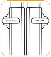
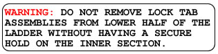
B.
The Lock Tab Assemblies- The second mechanical component of the ladder
system is the LOCK TAB
ASSEMBLY. There are four of these on each ladder. These permit you to change
the height of the ladder (See
figure B-1 and C-1). |
|
|
|
|
|
|
|
|
|
|
|
|
|
|
|
|
|
|
|
|
|
|
|
|
|
|
 |
|
 |
|
 |
|
|
|
|
|
|
|
|
|
|
|
|
 |
|
|
Figure
B-1 |
|
Figure
C-1 |
|
Figure
C-2 |
|
|
|
|
|
|
|
|
|
|
|
|
|
|
|
|
|
|
|
|
|
|
|
|
|
|
|
|
|
|
|
|
|
|
 |
|
|
|
 |
|
|
|
|
 |
|
|
|
|
|
|
|
|
|
|
|
|
|
|
|
|
|
|
|
|
|
|
|
|
|
|
|
|
|
|
|
|
|
|
|
|
|
|
|
|
|
|
|
|
|
| C.
Adjusting the height of the ladder for use in the A-frame position. |
|
|
|
|
|
|
|
|
|
|
|
|
|
|
|
|
|
|
|
|
|
|
|
|
|
|
|
|
|
|
|
|
|
|
|
|
|
1.
Unlock both hinge locks (See figures A-4 & A-5).
2. With the ladder in the storage position and while holding the inner ladder
assembly firmly in place, pull the four
Lock Tab Assemblies out of the rung holes of the inner ladder and rest them
on the side of the outer ladder rail
(See figures C-1).
3. Raise the inner ladder up to the desired height.
4. At the desired height align the outer holes with the nearest rung hole
of the inner ladder assembly. |
|
|
|
|
|
|
|
|
|
|
|
|
|
|
|
|
|
|
|
|
|
|
|
|
|
|
|
|
|
|
|
|
|
|
|
|
|
|
|
|
|
 |
|
|
|
|
|
|
|
|
|
|
|
|
|
|
|
|
|
|
|
|
|
|
|
|
|
|
|
|
|
|
|
|
|
|
|
|
|
|
|
|
|
|
|
|
|
|
|
|
|
|
|
|
|
|
|
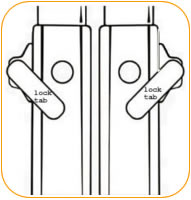
5.
Holding the inner and outer ladder at the aligned height with one hand,
reinsert the opposite Lock Tab Assemblies
into the rung holes with the other hand.
6. Alternate hands and perform the same operation with the other Lock Tab
Assemblies (See figure C-2). |
|
|
|
|
|
|
|
 |
|
|
|
|
|
|
|
|
|
|
|
|
|
|
|
|
|
|
|
|
7.
Open the ladder to the A-frame configuration by pulling the ladder halves
apart until the hinges lock into place
(See figure A-2 and A-4).
8. To return the ladder to the storage position, reverse the procedures
and position as seen in Figure A-1. |
|
|
|
|
|
|
|
|
|
|
|
|
|
|
|
|
|
|
|
|
|
|
|
|
|
|
|
|
|
|
|
|
|
|
|
|
|
| D.
Adjusting the height of the ladder in its extension ladder position. |
|
|
 |
|
|
|
|
|
|
|
|
|
|
|
|
|
|
|
|
|
|
|
|
|
|
|
|
|
|
|
|
|
|
1. From its stored position,
unlock hinge (as indicated in figures A-4 & A-5)
and rotate to extension position until both hinges lock into place.
NOTE: Hinge will first lock in A-frame position, repeat unlocking
hinge to
rotate its extension position. |
|
|
|
|
|
|
|
|
|
|
|
|
|
|
|
|
|
|
|
|
|
|
|
|
|
|
|
|
|
|
|
|
|
|
 |
|
|
|
|
|
|
|
|
|
|
|
|
|
|
|
|
|
|
|
|
|
|
|
|
|
|
|
|
|
|
Figure
D-1 |
|
|
|
|
|
|
|
|
|
|
|
|
|
|
|
|
|
|
|
|
|
|
|
|
|
|
|
|
|
|
|
|
|
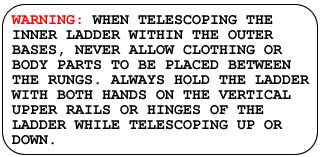
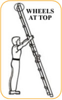
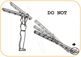
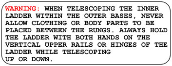
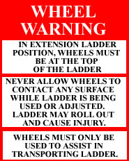
2.
If equipped with wheels, wheels must be at the top of the ladder while
in the extension position. Unlock Lock Tab Assemblies on upper half of
the ladder. Grasp the outer ladder, walk backward, allowing the ladder
to telescope to the desired height. If more height is desired, extend the
lower half of the ladder (see figure D-1). |
|
|
|
|
|
|
|
|
|
|
|
|
|
|
|
 |
|
|
|
|
|
|
|
|
|
|
|
|
|
|
|
|
|
|
|
|
|
 |
|
|
|
|
|
|
|
|
|
|
|
|
|
|
|
|
|
Figure
D-1A |
|
|
|
|
|
|
|
|
|
|
|
|
|
|
|
|
|
|
|
|
|
|
|
|
|
|
|
|
|
|
|
|
|
|
|
 |
 |
|
|
|
|
|
|
|
|
|
|
|
|
|
|
|
|
|
|
|
|
|
|
3.
To store the ladder from its extension position, reverse
the above sequence starting with the lower half of the
ladder. |
|
|
|
|
|
|
|
|
|
|
|
|
|
|
|
|
|
|
|
|
|
|
|
| E.
Staircase Position. |
|
|
|
|
|
|
|
|
|
|
|
|
|
|
|
|
|
|
|
|
|
|
|
|
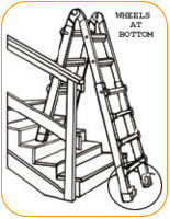
1.
Adjust ladder to desired height (review section
concerning adjusting the height of the ladder for use in the
A-frame position.) If equipped with wheels, the wheels
should be placed on the bottom of the long side, not against
the stairs. |
|
|
|
|
|
|
|
|
Figure
E-1 |
|
|
|
|
|
|
|
|
|
|
|
|
|
|
|
|
|
|
|
|
|
|
|
2.
Then adjust the side desired for proper alignment to fit the
staircase (see figure E-1). |
|
|
|
|
|
|
|
|
|
|
|
|
|
|
|
|
|
|
|
|
|
|
|
|
|
|
|
|
|
|
|
|
|
|
|
|
|
|
|
|
|
|
|
|
|
|
|
|
|
|
|
|
|
 |
|
|
|
|
 |
|
|
|
|
|
|
|
|
|
|
|
|
|
|
|
|
|
|
|
|
|
|
|
|
|
|
|
|
|
|
|
| F.
Scaffolding Trestle Operating Instructions |
|
|
|
|
|
|
|
|
|
|
|
|
|
|
|
|
|
|
|
|
|
|
|
|
|
|
|
|
|
|
|
|
|
|
|
|
|
|
|
|
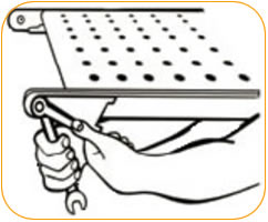
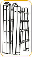
1.
Pull the inner ladder assembly completely out of the outer
ladder bases (see figure F-1). |
|
|
|
|
|
|
|
|
|
|
|
|
|
|
|
|
|
|
|
|
|
|
|
|
|
|
|
|
|
|
|
|
|
|
|
|
|
|
|
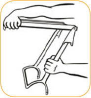
2.
Open the inner ladder assembly to the A-frame position until
both hinges lock (See figures A-4 and A-5). This is the first of
two trestles needed for the scaffolding function (see figure F-2). |
|
|
|
|
|
|
|
|
|
|
|
|
|
|
|
|
|
|
|
|
|
|
|
|
|
|
|
|
|
|
|
|
|
|
|
|
|
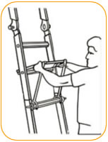
3.
Grasp both outer ladder bases (see figure F-3). |
|
|
|
|
|
|
|
|
|
|
|
|
|
|
|
|
|
|
|
|
|
|
|
|
|
|
|
|
|
|
|
|
|
|
|
|
|
|
|
|
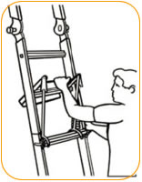
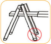
4.
If equipped with wheels, turn ladder without wheels 180º
and insert lock assemblies of that base into the adjacent holes
of the opposite outer base (see figure F-4). Wheels should be
facing out (see figure F-5). |
|
|
|
|
|
|
|
|
|
|
|
|
|
|
|
|
|
|
|
Figure
F-1 |
|
|
|
|
|
Figure
F-2 |
|
|
|
|
|
|
|
|
|
|
|
|
|
|
|
|
|
|
|
|
|
|
|
|
|
|
|
|
|
|
|
|
|
|
 |
|
|
 |
|
|
|
|
|
|
|
|
|
|
|
|
|
|
|
|
|
|
|
|
|
|
|
|
|
5.
Grasp the outer ladder base with the unused lock assemblies
and lower 1/2 inch, then spread the opposite outer ladder base
to form a second A-frame trestle (see figure F-5 and F-5
Close). |
|
|
|
|
|
|
|
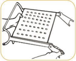
|
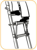
6.
Rotate forked ears on work platform to position indicated
in figure F-6. |
|
|
|
|
|
|
|
|
|
|
|
|
|
|
|
|
|
|
|
|
|
|
|
|
|
|
|
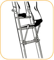
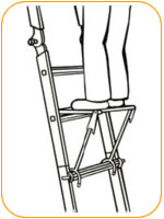
7.
Insert work platform between outer ladder bases on the
third rung down of each base. The wire-formed end of the
work platform should surround the outer rung turned to the
inside of the outer ladder A-frame trestle (see figure F-7). |
|
|
|
|
|
|
|
|
Figure
F-3 |
|
|
|
Figure
F-4 |
|
|
|
|
|
|
|
|
|
|
|
|
|
|
|
|
|
|
|
|
|
|
|
|
|
|
|
|
|
|
|
|
|
|
|
|
|
|
|
|
|
|
|
|
|
|
|
|
|
|
|
|
|
|
|
|
|
|
|
|
|
|
|
|
|
|
|
|
 |
|
 |
 |
|
|
|
|
|
|
|
|
|
|
|
|
|
|
|
|
 |
|
|
|
|
|
|
|
|
|
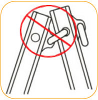
|
Figure
F-5 Close |
Doing this
step
incorrectly may cause
damage to ladder. |
|
|
|
|
|
|
|
|
|
|
|
|
|
|
|
|
|
|
|
|
|
Figure
F-6 |
|
|
|
|
|
|
|
|
|
|
|
|
|
|
|
|
|
|
|
|
|
|
|
|
|
|
|
|
|
|
|
|
|
|
|
|
|
|
|
|
|
|
|
|
|
|
|
|
|
|
|
|
|
|
|
|
|
|
|
|
|
|
|
|
|
|
|
|
|
|
 |
|
|
|
|
 |
|
|
|
|
|
|
|
|
|
|
|
|
|
|
|
|
|
|
|
|
|
|
 |
|
|
|
|
|
|
|
|
|
|
|
|
|
|
|
|
Wheels should
not be
on inside of trestle |
|
|
|
|
|
|
|
|
|
|
|
Figure
F-7 |
|
|
|
|
Figure
F-5 |
|
|
|
|
|
|
|
|
|
|
|
|
|
|
|
|
|
|
|
|
|
|
|
|
|
|
|
|
|
|
|
|
|
|
|
|
|
|
|
|
|
|
|
|
Little Giant 375 Ladder Systems
Type 1AA, Aluminum Step Ladder, Extension Ladder, used Safely on Stairs,
Ramps, Curbs, Docks or
other uneven surfaces, Aluminum, OSHA, 24 Different Ladders Combined,
A-Frame Ladder, Stair Access, Staircase Ladder, 90 Degree
Ladder, Extension Ladder, Scaffolding, and Telescoping Plank from your
source for material handling equipment. |
Back
to Product Category |
 |
|