
 |
ENGINEERED
STEEL PRODUCTS |
| Priced
Full Line Products Catalog |
20
Technology Way • West Greenwich, RI 02817
Toll free:(800) 421-0314 • In RI:(401) 272-4570 • Fax:(401)
421-5679 |
 |
|
|
 |
Back to Product Category
LiftAlloy BASKET TYPE CHAIN SLINGS
|
|
 |
|
|
|
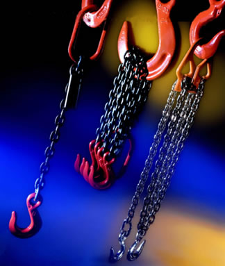
LiftAlloy Grade 80 chain slings
are recommended for rugged
industrial applications in harsh environments where flexibility,
abrasion resistance and long life are required. OSHA required
annual inspections can be performed by our trained personnel.
NOTE: Proof Coil Grad
30, High Test Grade 40 and Grade
70 transport tiedown chain and their fittings are not
recommended for listing or hoisting per ASME B30.9. |
|
|
|
FEATURES,
ADVANTAGES AND BENEFITS |
|
|
|
Promotes Safety
• Permanent steel capacity tag is serialized for identification
• Welded slings offer the security of tamper proof assemblies.
Saves Money
• Alloy Steel construction assures long lift.
• Can be repaired, proof tested and recertified.
Saves Time
• Easy to inspect for damage.
• Stores easily. |
|
HOW TO
ORDER CHAIN SLINGS |
|
|
|
|
|
| Specify: |
|
|
|
|
|
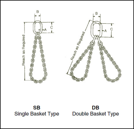
1. Chain Size - inches
2. Number of legs = (SB) Single Basket, (DB) Double Basket |
|
| 3.
Master Link (Type) - |
|
|
|
Oblong Link =
O
Grab Hook = G
Sling Hook = S |
|
|
|
|
LiftAlloy BASKET TYPE CHAIN SLINGS |
|
|
|
|
|
|
 |
|
|
|
|
|
|
|
|
 |
|
Order
Online, by Phone, or by E-Mail |
|
|
|
~ Add
items to your online shopping cart ~
Click a Price of the item you wish to purchase. |
|
|
|
|
|
|
|
PRICING - BASKET TYPE CHAIN SLINGS |
| Type
SB (CONTACT US FOR SPECIAL LENGTHS) |
Chain
Size
(in.) |
†Rated
Cap
(lbs.)
Grade 80 |
3' |
4' |
5' |
6' |
8' |
10' |
12' |
14' |
16' |
18' |
20' |
Add
per
foot of
extra
reach |
7/32 |
3,600 |
|
|
|
|
|
|
|
|
|
|
|
$20.54 |
9/32 |
6,100 |
|
|
|
|
|
|
|
|
|
|
|
$23.79 |
3/8 |
12,300 |
|
|
|
|
|
|
|
|
|
|
|
$34.94 |
1/2 |
20,800 |
|
|
|
|
|
|
|
|
|
|
|
$54.91 |
5/8 |
31,300 |
|
|
|
|
|
|
|
|
|
|
|
$79.71 |
3/4 |
49,000 |
|
|
|
|
|
|
|
|
|
|
|
$125.52 |
7/8 |
59,200 |
|
|
|
|
|
|
|
|
|
|
|
$195.11 |
1 |
82,600 |
|
|
|
|
|
|
|
|
|
|
|
$313.38 |
1
1/4 |
125,200 |
|
|
|
|
|
|
|
|
|
|
|
$592.26 |
Type
DB (CONTACT US FOR SPECIAL LENGTHS) |
7/32 |
5,450 |
|
|
|
|
|
|
|
|
|
|
|
$41.08 |
9/32 |
9,100 |
|
|
|
|
|
|
|
|
|
|
|
$47.57 |
3/8 |
18,400 |
|
|
|
|
|
|
|
|
|
|
|
$69.89 |
1/2 |
31,200 |
|
|
|
|
|
|
|
|
|
|
|
$109.81 |
5/8 |
47,000 |
|
|
|
|
|
|
|
|
|
|
|
$159.44 |
3/4 |
73,500 |
|
|
|
|
|
|
|
|
|
|
|
$251.04 |
7/8 |
88,900 |
|
|
|
|
|
|
|
|
|
|
|
$390.23 |
|
| NOTE: † Also referred to as "Working
Load Limit". |
|
|
|
|
* |
|
|
Do
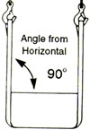
not exceed rated capacities. Sling capacity decreases as the angle from
horizontal decreases.
Slings should not be used at angles of less than 30°. Refer to chain
chart and Effect of Angle chart below. |
|
| Effect
of Angle of Lift on a Sling's Rated Capacity |
|
|
|
|
|
|
|
|
DEFINITION |
|
|
|
|
|
|
|
|
serves
to alert users to potentially hazardous situations which often occur in
the use of these products.
Failure to read, understand and follow the accompanying instructions on
how to avoid these situations
could result in death or serious injury. |
 |
|
|
|
|
Using
slings at an angle can become deadly if that angle is not taken into consideration
when selecting the sling
to be used. The tension on each leg of the sling is increased as the angle
of lift, from horizontal, decreases. It is
most desirable for a sling to have a larger angle of lift, approaching 90°.
Lifts with angles of less than 30° from
horizontal are not recommended. If you can measure the angle of lift or
the length and height of the sling as rigged,
you can determine the properly rated sling for your lift. |
|
|
|
|
|
|
|
|
|
|
|
|
|
|
|
What
would be the rating of each sling
rigged at this angle? |
|
|
 |
|
 |
|
What
capacity sling do I need? |
|
|
|
|
|
|
|
|
|
|
|
|
1.
Determine the weight that the sling
will be lifting [LW]. |
|
|
|
|
|
|
|
| 1.
Calculate the Reduction Factor [RF]. |
|
|
|
|
|
|
|
|
|
|
|
|
|
|
|
|
a.
Using the angle from horizontal,
read across the Angle Chart to the
corresponding number of the
Reduction Factor column. |
|
|
|
|
2.
Calculate the Tension Factor [TF]. |
|
|
|
|
|
|
|
|
|
|
|
|
|
|
|
a.
Using the angle from horizontal,
read across the angle chart to the
corresponding number of Tension
Factor column. |
|
|
|
|
|
|
|
|
|
-OR- |
|
|
|
|
|
|
|
|
|
|
|
|
|
|
|
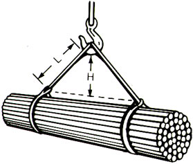
b.
Divide sling height* [H] by sling
length* [L]. |
|
|
|
|
|
|
|
|
|
|
|
|
|
|
-OR- |
|
|
|
|
|
|
|
|
|
|
|
|
|
|
|
b.
Divide sling height* [H] by sling
length* [L]. |
|
|
|
|
|
Choker
Hitch |
|
Vertical
Hitch |
2.
Reduction Factor [RF] x the sling's
rated capacity for the type hitch that
will be used = Sling's Reduced Rating. |
|
|
|
|
|
|
|
|
|
|
|
|
|
|
|
 |
|
|
|
|
|
|
|
|
|
|
|
|
|
|
|
|
|
3.
Lifting Weight [LW] x the Tension
Factor [TF] = Minimum Sling Rating
for the type of hitch that will be used. |
|
|
|
Vertical
Basket
Hitch |
|
|
*Measured
from a common horizontal plane to
the hoisting hook. |
|
|
|
|
|
|
|
|
|
|
|
*Measured
from a common horizontal
plane to the hoisting hook. |
|
|
|
|
|
|
|
|
|
|
|
|
|
|
|
|
|
|
|
|
|
|
|
|
|
|
|
Reduced
Capacity |
|
|
|
|
|
|
|
|
|
|
Effect
of Angle Chart |
|
Increasing
Tension |
 |
|
|
|
Reduction
Factor |
Angle
From
Horizontal |
Tension
Factor
(TF) |
| 1.000 |
90º |
1.000 |
| 0.996 |
85º |
1.004 |
| 0.985 |
80º |
1.015 |
| 0.966 |
75º |
1.035 |
| 0.940 |
70º |
1.064 |
| 0.906 |
65º |
1.104 |
| 0.866 |
60º |
1.155 |
| 0.819 |
55º |
1.221 |
| 0.766 |
50º |
1.305 |
| 0.707 |
45º |
1.414 |
| 0.643 |
40º |
1.555 |
| 0.574 |
35º |
1.742 |
| 0.500 |
30º |
2.000 |
|
|
 |
Example:
Vertical Choker rating of each sling = 6,000 lbs.
Measured Length (L) = 6 ft.
Measured Height (H) = 4 ft.
Reduction Factor (RF) = 4 (H) ÷ 6 (L) = .667
Reduced sling rating in this configuration = .667
(RF) x 6,000 lbs. = 4,000 lbs. of lifting capacity
per sling |
|
|
|
|
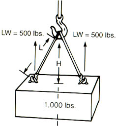
Example:
Load Weight = 1,000 lbs.
Rigging - 2 slings in vertical hitch
Lifting Weight (LW) per sling = 500 lbs.
Measured Length (L) = 10 ft.
Measured Height (H) = 5 ft.
Tension Factor (TF) = 10 (L) ÷ 5 (H) = 2.0
Minimum Vertical Rated Capacity required
for this lift = 500 (LW) x 2.0 (TF) = 1,000
lbs. per sling |
|
Sling
capacity decreases as the angle
from horizontal decrease. Sling angles
of less than 30° are not recommended. |
|
|
|
|
|
|
|
|
|
|
|
|
|
|
|
|
|
|
|
|
|
LiftAlloy Single Chain Slings,
Lift-All, Sling, Lifting Slings, Sling Hook, Grab Hook, Foundry Hook,
Latch Hook, Double
Chain Slings, Triple Chain Slings, Quad Chain Slings, and Basket Type
Chain Slings from your source for material
handling equipment. |
Back
to Product Category |
 |
|


