
 |
ENGINEERED
STEEL PRODUCTS |
| Priced
Full Line Products Catalog |
20
Technology Way • West Greenwich, RI 02817
Toll free:(800) 421-0314 • In RI:(401) 272-4570 • Fax:(401)
421-5679 |
|
|
|
|
Back
to Product Category
ELECTRIC
HEATED AIR CURTAINS
|
|
| FREE
FREIGHT |
| FOR
ALL AIR CURTAINS SHIPPED TO LOCATIONS WITHIN THE 48 CONTIGUOUS UNITED STATES |
|
|
|
|
|
|
|
|
|
|
|
 |
|
|
|
|
Q |
The first question is, do I really need a heated
air curtain? |
| A |
The answer is maybe not. Air doors effectively
create an efficient insulation barrier between
two environments. It's approximately 80% -
90% efficient. It does so by creating a stiff
blast of air blowing down from the unit towards
the floor. This blast of air create an invisible
barrier separating the two environments.
If you have people working near or walking
through this moving air, they may feel a breeze.
This could cause a wind chill effect, similar to
the cooling effects of a blowing fan during the
summer. Adding a heated air curtain unit will
minimize this effect and make for a comfortable
and more productive work place for your
employees and customers.
Should your facility be located in a cold weather
environment creating significant temperature
differences between the outside versus the
inside temperature, a heated unit will signi-
ficantly improve the work environment comfort
level and help maintain consistent temperature
control. In addition, it will reduce overall utility
and maintenance costs by providing a more
constant inside temperature. |
|
|
|
|
|
|
|
|
|
|
|
|
|
 |
|
|
|
|
|
|
|
|
|
|
|
|
|
|
|
| TYPICAL
USES |
|
|
|
|
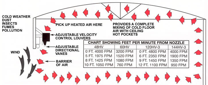
Easily
mounted over entrance ways of warehouse
doors up to 16 feet high, the air curtains direct an
invisible stream of stratified heated air downward. In
addition to adding to employee and customer comfort
during cold weather they provide important energy
savings in three ways: |
|
|
|
|
|
|
|
|
|
|
|
|
|
1.
In cold weather they reduce the load on heating
systems. By drawing warm air down to floor level
where it is needed, our air curtains utilize the 50%
of wasted heated air trapped under ceilings. Stratified
air is mixed and circulated with building heat and heat
given off by lights and machinery, etc. |
|
|
|
|
|
|
|
|
|
|
|
ENERGY |
|
|
Our
air curtains conserve energy and improve comfort by
limiting the escape of internal heat, reducing cold drafts
and providing a welcoming down flow curtain of warm
air at entrance ways in industrial plants and store buildings.
The resulting mixture of warmed air disperses gently in
all directions at floor level to give uniform temperature
over a wide area from floor to ceiling with only a few
degrees difference. |
|
|
|
|
|
|
|
2.
The high velocity curtain of air deflects winds and
reduces excessive heat loss through open doorways. |
|
|
|
|
|
|
|
|
|
3.
During warm weather they can direct a stream of air
downward to help keep dust, dirt, insects and fumes from
entering through open doorways. If air conditioning exists
in the building during warm weather, the air curtains can
be used to prevent loss of conditioned air as well. |
|
|
|
|
|
|
|
|
|
CONVENIENCE |
|
Our
air curtains allow personnel and cargo to pass freely
from one area to another while maintaining desired
temperatures. |
|
|
|
|
|
|
|
|
|
|
|
|
|
|
|
|
|
|
|
|
|
|
|
An
added safety feature is the free flow of traffic with an
unobstructed view through the opening, eliminating
doorway accidents. |
|
|
|
|
|
|
|
Our
air curtains create an invisible barrier of high velocity
air to stop cold or warm air infiltrating plant facilities and
work areas. |
 Stop entry of cold or warm air when doors are open. Stop entry of cold or warm air when doors are open. |
|
Prevent the possibility of accidents with unobstructed
view of passageways. |
|
IMPORTANT:
MUST BE INSTALLED ON WARM
SIDE OF DOORWAY OPENING WHEN USED FOR
TEMPERATURE CONTROL |
Eliminate need for expensive plastic stripping, flapper
doors, or canvas curtains. |
|
Cold
weather can be further deterred at door opening if
space heater in plant is directed toward intake of the air
curtain. |
|
|
|
|
|
|
|
|
|
|
 |
|
|
|
|
|
|
|
|
|
| SPECIFICATIONS
AND FEATURES |
|
|
|
|
|
|
|
| FOR
ARCHITECTS AND ENGINEERS |
|
EASY
INSTALLATION |
Our
air curtains shall have a self-contained one piece
housing, fire retardant and corrosion proof, incorporated
with a double extended shaft motor, direct drive double
width and double inlet squirrel cage blower wheels and
fan housings. |
Our
air curtains are bolted to wall with four fasteners and
connected to electric power source. |
AIR
VELOCITY CONTROL FOR VARIABLE AIR
SPEED |
Shall
have wedge shaped discharge nozzle containing
adjustable air deflectors with 40% sweep front to back. |
|
Adjustable
louver damper controls are provided in order
to adjust rate of air flow. |
Housing
shall be sufficient strength for fastening to wall
on both ends without any intermediate support. |
|
When
used over a doorway to retain warm or cold
temperature, proper velocity adjustment is imperative
for maximum efficiency. Velocity Control can reduce
air velocity up to 60% with louvers in totally closed
position. |
| HEAVY
DUTY ELECTRIC MOTOR |
|
Continuous
duty type motor with double sealed lifetime
pre-lubricated stainless steel ball bearings, resilient
mounted and protected by an automatic thermal over-
load switch. Underwriters Laboratories Listed and
Canadian Standards Association Certified. Explosion
proof motors available. |
|
|
AIR
DIRECTIONAL CONTROL |
|
Adjustable
vanes at outlet nozzle for directing air
to compensate for possible draft conditions
through doorways. |
|
|
|
|
|
|
|
| FIRE
RETARDANT AND CORROSION PROOF |
|
|
|
|
|
Steel
models are of 18 gauge paint lock metal and double
protected with gray, baked, rust preventative electrostatic
polyurethane powder coating. |
|
|
|
|
How Air
Curtain Works! |
|
| NOISE
LEVEL |
|
|
|
|
|
|
|
 |
|
Our
air curtains operate under a low noise level in the interest
and comfort of personnel working in the immediate vicinity. |
|
|
|
|
|
|
|
|
|
 |
|
|
|
|
SELECTION
TABLE |
Model
No. |
Width
of Door |
Door
Height |
FLA
(Ampacity) Single Phase |
Sound
dBA |
Weight
(lbs) |
115V |
208V/230V |
STD236 |
36" |
8'
- 10' |
5.1 |
2.5
/ 2.5 |
66 |
50 |
STD242 |
42" |
8'
- 10' |
5.1 |
2.5
/ 2.5 |
66 |
55 |
STD248 |
48" |
8'
- 10' |
5.1 |
2.5
/ 2.5 |
66 |
60 |
STD264-2 |
64" |
8'
- 10' |
10.2 |
5.0
/ 5.0 |
68 |
95 |
STD272-2 |
72" |
8'
- 10' |
10.2 |
5.0
/ 5.0 |
68 |
100 |
STD278-2 |
78" |
8'
- 10' |
10.2 |
5.0
/ 5.0 |
68 |
110 |
STD284-2 |
84" |
8'
- 10' |
10.2 |
5.0
/ 5.0 |
68 |
115 |
STD296-2 |
96" |
8'
- 10' |
10.2 |
5.0
/ 5.0 |
68 |
125 |
STD296-3 |
96" |
8'
- 10' |
15.3 |
7.5
/ 7.5 |
71 |
170 |
STD2108-2 |
108" |
8'
- 10' |
10.2 |
5.0
/ 5.0 |
71 |
130 |
STD2108-3 |
108" |
8'
- 10' |
15.3 |
7.5
/ 7.5 |
71 |
175 |
STD2120-3 |
120" |
8'
- 10' |
15.3 |
7.5
/ 7.5 |
71 |
185 |
STD2144-3 |
144" |
8'
- 10' |
15.3 |
7.5
/ 7.5 |
71 |
205 |
STD2144-4 |
144" |
8'
- 10' |
20.4 |
10.0
/ 10.0 |
73 |
215 |
HV242 |
42" |
10'
- 12' |
3.3
/ 3.2 |
1.6 |
70 |
90 |
HV248 |
48" |
10'
- 12' |
3.3
/ 3.2 |
1.6 |
70 |
95 |
HV260 |
60" |
10'
- 12' |
3.3
/ 3.2 |
1.6 |
70 |
105 |
HV272-2 |
72" |
10'
- 12' |
6.6
/ 6.4 |
3.2 |
73 |
165 |
HV284-2 |
84" |
10'
- 12' |
6.6
/ 6.4 |
3.2 |
73 |
180 |
HV296-2 |
96" |
10'
- 12' |
6.6
/ 6.4 |
3.2 |
73 |
190 |
HV296-3 |
96" |
10'
- 12' |
9.9
/ 9.6 |
4.8 |
75 |
240 |
HV2108-2 |
108" |
10'
- 12' |
6.6
/ 6.4 |
3.2 |
73 |
200 |
HV2108-3 |
108" |
10'
- 12' |
9.9
/ 9.6 |
4.8 |
75 |
255 |
HV2120-2 |
120" |
10'
- 12' |
6.6
/ 6.4 |
3.2 |
73 |
215 |
HV2120-3 |
120" |
10'
- 12' |
9.9
/ 9.6 |
4.8 |
75 |
270 |
HV2144-3 |
144" |
10'
- 12' |
9.9
/ 9.6 |
4.8 |
75 |
295 |
HV2144-4 |
144" |
10'
- 12' |
13.2
/ 12.8 |
6.4 |
75 |
375 |
|
|
 |
|
|
|
 |
|
MODEL NUMBER
CONFIGURATION |
|
 |
|
|
|
|
 |
|
Order
Online, by Phone, or by E-Mail |
|
|
|
~ Add
items to your online shopping cart ~
Click the Model No. of the item you wish
to purchase. |
|
|
|
|
|
|
|
| Standard
Features: |
½
hp direct-drive motor
Sleek metal design
Easy install
Motor fan assembly
18-month warranty |
Made in USA |
Standard
Color: |
|
|
 |
|
|
Protection
Environmental: 10’
Flying-insects: 8’ |
|
|
|
|
|
PRICING
AND SPECIFICATIONS (ELECTRIC HEATED MODELS) |
Full
freight allowed. Prices included delivery to any destination within the
Continental United States or to Port of
Embarkation for Overseas shipments. |
|
IMMEDIATE
FREE DELIVERY MADE WITH PRIDE IN THE USA |
|
ELECTRIC
HEATED STANDARD SERIES PRICES |
Models |
Voltage |
kW |
Air
Volume
(max.) |
Length |
Height |
Depth |
Full
Load
Draw |
Wgt.
(lbs) |
Avg.
Velocity |
#
of
motors |
PRICE |
|
208/1/60 |
6kW |
1379cfm |
36" |
10
5/8" |
17
3/8" |
31amps |
90 |
2206fpm |
1 |
$2,611 |
|
230/1/60 |
6kW |
1379cfm |
36" |
10
5/8" |
17
3/8" |
29amps |
90 |
2206fpm |
1 |
$2,611 |
|
208/3/60 |
12kW |
1379cfm |
36" |
10
5/8" |
17
3/8" |
36amps |
90 |
2206fpm |
1 |
$2,611 |
|
230/3/60 |
12kW |
1379cfm |
36" |
10
5/8" |
17
3/8" |
33amps |
90 |
2206fpm |
1 |
$2,611 |
|
460/3/60 |
12kW |
1379cfm |
36" |
10
5/8" |
17
3/8" |
16amps |
90 |
2206fpm |
1 |
$2,611 |
|
208/1/60 |
6kW |
1418cfm |
42" |
10
5/8" |
17
3/8" |
31amps |
95 |
1945fpm |
1 |
$2,703 |
|
230/1/60 |
6kW |
1418cfm |
42" |
10
5/8" |
17
3/8" |
29amps |
95 |
1945fpm |
1 |
$2,703 |
|
208/3/60 |
12kW |
1418cfm |
42" |
10
5/8" |
17
3/8" |
36amps |
95 |
1945fpm |
1 |
$2,703 |
|
230/3/60 |
12kW |
1418cfm |
42" |
10
5/8" |
17
3/8" |
33amps |
95 |
1945fpm |
1 |
$2,703 |
|
460/3/60 |
12kW |
1418cfm |
42" |
10
5/8" |
17
3/8" |
16amps |
95 |
1945fpm |
1 |
$2,703 |
|
208/1/60 |
6kW |
1442cfm |
48" |
10
5/8" |
17
3/8" |
31amps |
100 |
1730fpm |
1 |
$2,738 |
|
230/1/60 |
6kW |
1442cfm |
48" |
10
5/8" |
17
3/8" |
29amps |
100 |
1730fpm |
1 |
$2,738 |
|
208/3/60 |
12kW |
1442cfm |
48" |
10
5/8" |
17
3/8" |
36amps |
100 |
1730fpm |
1 |
$2,738 |
|
230/3/60 |
12kW |
1442cfm |
48" |
10
5/8" |
17
3/8" |
33amps |
100 |
1730fpm |
1 |
$2,738 |
|
460/3/60 |
12kW |
1442cfm |
48" |
10
5/8" |
17
3/8" |
16amps |
100 |
1730fpm |
1 |
$2,738 |
|
208/1/60 |
6kW |
2700cfm |
60" |
10
5/8" |
17
3/8" |
63amps |
115 |
2592fpm |
1 |
$4,396 |
|
230/1/60 |
6kW |
2700cfm |
60" |
10
5/8" |
17
3/8" |
57amps |
115 |
2592fpm |
1 |
$4,396 |
|
208/3/60 |
12kW |
2700cfm |
60" |
10
5/8" |
17
3/8" |
72amps |
115 |
2592fpm |
1 |
$4,396 |
|
230/3/60 |
12kW |
2700cfm |
60" |
10
5/8" |
17
3/8" |
65amps |
115 |
2592fpm |
1 |
$4,396 |
|
460/3/60 |
12kW |
2700cfm |
60" |
10
5/8" |
17
3/8" |
31amps |
115 |
2592fpm |
1 |
$4,396 |
|
208/1/60 |
12kW |
2758cfm |
72" |
10
5/8" |
17
3/8" |
63amps |
180 |
2206fpm |
2 |
$4,867 |
|
230/1/60 |
12kW |
2758cfm |
72" |
10
5/8" |
17
3/8" |
57amps |
180 |
2206fpm |
2 |
$4,867 |
|
208/3/60 |
24kW |
2758cfm |
72" |
10
5/8" |
17
3/8" |
72amps |
180 |
2206fpm |
2 |
$4,867 |
|
230/3/60 |
24kW |
2758cfm |
72" |
10
5/8" |
17
3/8" |
65amps |
180 |
2206fpm |
2 |
$4,867 |
|
460/3/60 |
24kW |
2758cfm |
72" |
10
5/8" |
17
3/8" |
31amps |
180 |
2206fpm |
2 |
$4,867 |
|
208/1/60 |
12kW |
2836cfm |
84" |
10
5/8" |
17
3/8" |
63amps |
190 |
1945fpm |
2 |
$5,061 |
|
230/1/60 |
12kW |
2836cfm |
84" |
10
5/8" |
17
3/8" |
57amps |
190 |
1945fpm |
2 |
$5,061 |
|
208/3/60 |
24kW |
2836cfm |
84" |
10
5/8" |
17
3/8" |
72amps |
190 |
1945fpm |
2 |
$5,061 |
|
230/3/60 |
24kW |
2836cfm |
84" |
10
5/8" |
17
3/8" |
65amps |
190 |
1945fpm |
2 |
$5,061 |
|
460/3/60 |
24kW |
2836cfm |
84" |
10
5/8" |
17
3/8" |
31amps |
190 |
1945fpm |
2 |
$5,061 |
|
208/1/60 |
12kW |
2884cfm |
96" |
10
5/8" |
17
3/8" |
63amps |
225 |
1730fpm |
2 |
$5,171 |
|
230/1/60 |
12kW |
2884cfm |
96" |
10
5/8" |
17
3/8" |
57amps |
225 |
1730fpm |
2 |
$5,171 |
|
208/3/60 |
24kW |
2884cfm |
96" |
10
5/8" |
17
3/8" |
72amps |
225 |
1730fpm |
2 |
$5,171 |
|
230/3/60 |
24kW |
2884cfm |
96" |
10
5/8" |
17
3/8" |
65amps |
225 |
1730fpm |
2 |
$5,171 |
|
460/3/60 |
24kW |
2884cfm |
96" |
10
5/8" |
17
3/8" |
31amps |
225 |
1730fpm |
2 |
$5,171 |
|
460/3/60 |
36kW |
4137cfm |
108" |
10
5/8" |
17
3/8" |
47amps |
270 |
2206fpm |
3 |
$6,585 |
|
460/3/60 |
36kW |
4341cfm |
120" |
10
5/8" |
17
3/8" |
47amps |
280 |
2084fpm |
3 |
$6,696 |
|
460/3/60 |
36kW |
4326cfm |
144" |
10
5/8" |
17
3/8" |
47amps |
330 |
1730fpm |
3 |
$6,805 |
|
|
 |
|
OB |
|
TS |
|
PW |
|
|
|
|
|
|
|
|
| Optional
Color Available - Std. Production Color is Obsidian Black (matte) See add-on prices below. |
|
|
|
|
|
|
|
Prices
for Colors That are not Standard for the Series
(add these prices to price of electric heated
standard air curtain) |
| Length of Unit |
25" |
36" |
42" |
48" |
60" |
64" |
72" |
84" |
96" |
108" |
120" |
144" |
| TS |
|
|
|
|
|
|
|
|
|
|
|
|
| PW |
|
|
|
|
|
|
|
|
|
|
|
|
|
|
|
|
|
|
|
|
|
Full
freight allowed. Prices included delivery to any destination within the
Continental United States or to Port of
Embarkation for Overseas shipments. |
|
|
|
|
|
IMMEDIATE
FREE DELIVERY MADE WITH PRIDE IN THE USA |
|
|
|
|
|
| Standard
Features: |
Standard Color: |
|
1
hp direct-drive motor
Sleek metal design
Easy install
Motor fan assembly
18-month warranty
Made in USA |
|
Protection
Environmental: 12’
Flying-insects: 10’ |
 |
|
|
|
|
|
|
|
|
|
|
MODEL
NUMBER CONFIGURATION |
 |
|
|
|
|
 |
|
|
|
|
|
|
Order
Online, by Phone, or by E-Mail |
|
|
|
~ Add
items to your online shopping cart ~
Click the Model No. of the item you wish
to purchase. |
|
|
ELECTRIC
HEATED HIGH VELOCITY MODELS PRICES |
Models |
Voltage |
kW |
Air
Volume (max.) |
Length |
Height |
Depth |
Full
Load Draw |
Wgt.
(lbs) |
Avg.
Velocity |
#
of
motors |
PRICE |
|
208/1/60 |
6kW |
2447cfm |
48" |
14" |
21
3/8" |
32amps |
145 |
2447fpm |
1 |
$3,353 |
|
230/1/60 |
6kW |
2447cfm |
48" |
14" |
21
3/8" |
29amps |
145 |
2447fpm |
1 |
$3,353 |
|
208/3/60 |
12kW |
2447cfm |
48" |
14" |
21
3/8" |
37amps |
145 |
2447fpm |
1 |
$3,353 |
|
230/3/60 |
12kW |
2447cfm |
48" |
14" |
21
3/8" |
33amps |
145 |
2447fpm |
1 |
$3,353 |
|
460/3/60 |
12kW |
2447cfm |
48" |
14" |
21
3/8" |
17amps |
145 |
2447fpm |
1 |
$3,353 |
|
208/1/60 |
6kW |
2760cfm |
48" |
14" |
21
3/8" |
32amps |
155 |
2208fpm |
1 |
$3,424 |
|
230/1/60 |
6kW |
2760cfm |
48" |
14" |
21
3/8" |
29amps |
155 |
2208fpm |
1 |
$3,424 |
|
208/3/60 |
12kW |
2760cfm |
60" |
14" |
21
3/8" |
37amps |
155 |
2208fpm |
1 |
$3,424 |
|
230/3/60 |
12kW |
2760cfm |
60" |
14" |
21
3/8" |
33amps |
155 |
2208fpm |
1 |
$3,424 |
|
460/3/60 |
12kW |
2760cfm |
60" |
14" |
21
3/8" |
17amps |
155 |
2208fpm |
1 |
$3,424 |
|
208/1/60 |
12kW |
3584cfm |
48" |
14" |
21
3/8" |
64amps |
315 |
2389fpm |
2 |
$6,369 |
|
230/1/60 |
12kW |
3584cfm |
48" |
14" |
21
3/8" |
59amps |
315 |
2389fpm |
2 |
$6,369 |
|
208/3/60 |
24kW |
3584cfm |
72" |
14" |
21
3/8" |
73amps |
315 |
2389fpm |
2 |
$6,369 |
|
230/3/60 |
24kW |
3584cfm |
72" |
14" |
21
3/8" |
67amps |
315 |
2389fpm |
2 |
$6,369 |
|
460/3/60 |
24kW |
3584cfm |
72" |
14" |
21
3/8" |
33amps |
315 |
2389fpm |
2 |
$6,369 |
|
208/1/60 |
12kW |
4644cfm |
48" |
14" |
21
3/8" |
64amps |
335 |
2654fpm |
2 |
$6,467 |
|
230/1/60 |
12kW |
4644cfm |
48" |
14" |
21
3/8" |
59amps |
335 |
2654fpm |
2 |
$6,467 |
|
208/3/60 |
24kW |
4644cfm |
84" |
14" |
21
3/8" |
73amps |
335 |
2654fpm |
2 |
$6,467 |
|
230/3/60 |
24kW |
4644cfm |
84" |
14" |
21
3/8" |
67amps |
335 |
2654fpm |
2 |
$6,467 |
|
460/3/60 |
24kW |
4644cfm |
84" |
14" |
21
3/8" |
33amps |
335 |
2654fpm |
2 |
$6,467 |
|
208/1/60 |
12kW |
4894cfm |
48" |
14" |
21
3/8" |
64amps |
340 |
2447fpm |
2 |
$6,545 |
|
230/1/60 |
12kW |
4894cfm |
48" |
14" |
21
3/8" |
59amps |
340 |
2447fpm |
2 |
$6,545 |
|
208/3/60 |
24kW |
4894cfm |
96" |
14" |
21
3/8" |
73amps |
340 |
2447fpm |
2 |
$6,545 |
|
230/3/60 |
24kW |
4894cfm |
96" |
14" |
21
3/8" |
67amps |
340 |
2447fpm |
2 |
$6,545 |
|
460/3/60 |
24kW |
4894cfm |
96" |
14" |
21
3/8" |
33amps |
340 |
2447fpm |
2 |
$6,545 |
|
460/3/60 |
36kW |
5376cfm |
108" |
14" |
21
3/8" |
50amps |
425 |
2389fpm |
3 |
$8,725 |
|
208/1/60 |
12kW |
5519cfm |
48" |
14" |
21
3/8" |
64amps |
365 |
2208fpm |
2 |
$6,688 |
|
230/1/60 |
12kW |
5519cfm |
48" |
14" |
21
3/8" |
59amps |
365 |
2208fpm |
2 |
$6,688 |
|
208/3/60 |
24kW |
5519cfm |
120" |
14" |
21
3/8" |
73amps |
365 |
2208fpm |
2 |
$6,688 |
|
230/3/60 |
24kW |
5519cfm |
120" |
14" |
21
3/8" |
67amps |
365 |
2208fpm |
2 |
$6,688 |
|
460/3/60 |
24kW |
5519cfm |
120" |
14" |
21
3/8" |
33amps |
365 |
2208fpm |
2 |
$6,688 |
|
460/3/60 |
36kW |
6693cfm |
120" |
14" |
21
3/8" |
50amps |
440 |
2678fpm |
3 |
$8,823 |
|
460/3/60 |
36kW |
7341cfm |
144" |
14" |
21
3/8" |
50amps |
465 |
2447fpm |
3 |
$8,991 |
|
|
|
|
OB |
|
TS |
|
PW |
|
|
|
|
|
|
|
|
|
| Optional
Color Available - Std. Production Color is Titanium Silver See
add-on prices below. |
|
|
|
|
|
|
|
|
|
|
Prices
for Colors That are not Standard for the Series (add
these prices to price of standard air curtain) |
| Length of Unit |
25" |
36" |
42" |
48" |
60" |
64" |
72" |
84" |
96" |
108" |
120" |
144" |
OB |
|
|
|
|
|
|
|
|
|
|
|
|
| PW |
|
|
|
|
|
|
|
|
|
|
|
|
|
|
|
 |
|
Order
Online, by Phone, or by E-Mail |
|
|
|
~ Add
items to your online shopping cart ~
Click the Part No. of the item you wish to
purchase. |
|
|
|
ACCESSORIES
- Electric Heated |
|
| DOOR
SWITCHES |
| Automatic
on/off control of air curtain as door is opened and closed |
| LINE
VOLTAGE |
| Part No. |
Package |
Price |
|
Steel Mechanical
Universal Surface-Mounted Plunger/Roller Switch |
$141.50 |
| 24-Volt
Control |
|
Industrial
Floor-Mounted Magnetic Reed Switch Only - Floor mounted.
Note: Control panel required. |
$330.30 |
|
Industrial
Surface-Mounted Magnetic Reed Switch Only.
Surface-mounted.
Note: Control panel required. |
$330.30 |
|
|
| CONTROL
PACKAGES |
| Combination
packages of door switches, controllers, time delays, and thermostats |
| LINE
VOLTAGE |
| Part No. |
Package |
Price |
|
Analog
Thermostat - Remote-mounted |
$165.10 |
|
| OPTIONAL CONTROLS - Can be paired with any control package |
Part No. |
Package |
Price |
|
Master/Slave
Control with Single Thermostat |
$198.20 |
|
MOUNTING BRACKETS |
| Part No. |
Mounting Bracket |
Price |
Recommended
for specific applications · Standard color Titanium Silver
· NOTE: Units come standard with predrilled holes on back end
for flush mounting |
|
5"
Flat Side Extension Plates - to clear track
on either end - Set of 2 |
$165.10 |
|
7"
Flat Side Extension Plates - to clear track
on either end - Set of 2 |
$165.10 |
|
9"
Flat Side Extension Plates - to clear track
on either end - Set of 2 |
$165.10 |
|
2
1/2"-Clearance Adjustable-Angle Mounting Bracket To clear wall obstructions - Set of 2 |
$165.10 |
|
4"-Clearance
Adjustable-Angle Mounting Bracket To clear
wall obstructions - Set of 2 |
$330.30 |
|
7"-Clearance
Adjustable-Angle Mounting Bracket To clear
wall obstructions - Set of 2 |
$330.30 |
|
10"-Clearance
Adjustable-Angle Mounting Bracket To clear
wall obstructions - Set of 2 |
$330.30 |
|
10"-Clearance
Drum-Roll-Style Extended Wall Mounting Bracket
For use over drum-style roll-up doors - Set
of 2 |
$396.30 |
|
16"-Clearance
Drum-Roll-Style Extended Wall Mounting Bracket
For use over drum-style roll-up doors - Set
of 2 |
$396.30 |
|
19"-Clearance
Drum-Roll-Style Extended Wall Mounting Bracket
For use over drum-style roll-up doors - Set
of 2 |
$418.30 |
|
23"-Clearance
Drum-Roll-Style Extended Wall Mounting Bracket
For use over drum-style roll-up doors - Set
of 2 |
$506.40 |
|
| FILTERS |
| Part No. |
Filters |
Price |
| FLTR |
HV2 Aluminum Mesh Filter 1/4'
Internal-mount - Set of 2 - (size): Specify size in inches |
$3.10/per inch |
|
|
|
1/2
HP STANDARD HEATED MODELS DRAWING |
|
|
|
|
|
|
 |
NOTES: |
|
1.
This product is designed to meet the National
Electric Code (NEC) and is ETL Listed for the
US and Canada and bear the CE Mark. |
|
2.
7/16" mounting holes (4) provided, (2) on each
end, 1/2" key hole slots (2) provided, (1)
on each
end for wall mounting. |
|
3.
All units have a self contained one piece cabinet,
fire retardant and corrosion proof paint lock metal,
double protected with baked on Obsidian Black
color rust preventative electrostatic polyurethane
powder coating. |
|
4.
Cabinet has sufficient strength for suspension
from both ends without intermediate support. |
|
5.
Control panel is prewired and premounted inside
the cabinet. Optional remote mounted available. |
|
6.
Unit is to be installed such that air flow is unob-
structed. Air discharge nozzle containing adjustable
air directional vanes with 40° sweep front to back. |
|
7.
Wall mounted 24 volt thermostat with remote"heat/
off/fan" switch shipped loose and field installed.
Terminal block provided inside panel. |
|
| 8.
Branch circuit protected as per NEC by others. |
|
9.
Optional door limit switch is field installed and is
to be wired to the control panel. Switch to be
mounted such that the air curtain turns on as door
begins to open. A time delay is highly re-
commended with the optional door limit switch. |
|
|
|
|
|
|
|
|
|
|
|
|
|
|
|
|
|
|
|
|
|
|
|
|
|
*NOTE: Intake screen size and number varies with unit length. |
| -2
&-3 designates the number of motors. |
|
|
|
|
|
|
|
|
 |
|
Model
No. |
Mounting
Centers
A |
Length
B |
STD236-1E |
35
1/8" |
36" |
STD242-1E |
41
1/8" |
42" |
STD248-1E |
47
1/8" |
48" |
STD260-1E |
59
1/8" |
60" |
STD260-2E |
59
1/8" |
60" |
STD264-2E |
63
1/8" |
64" |
STD272-2E |
71
1/8" |
72" |
STD278-2E |
77
1/8" |
78" |
STD284-2E |
83
1/8" |
84" |
STD296-2E |
95
1/8" |
96" |
STD296-3E |
95
1/8" |
96" |
STD2108-3E |
107
1/8" |
108" |
STD2120-3E |
119
1/8" |
120" |
STD2144-3E |
143
1/8" |
144" |
STD2144-4E |
143
1/8" |
144" |
|
|
|
|
|
TYPICAL
INSTALLATION |
|
1.
Connect supply voltage from power panel to control panel. (8)
2. Connect wires from motor leads in junction box to terminals
in panel per print.
3. Connect wires from door limit switch to terminals in panel
per print.
4. Check rotation of motors and switch leads if necesary to
correct. |
|
|
HIGH
VELOCITY AND EXTRA POWER ELECTRIC HEATED MODELS DRAWING |
|
|
|
|
|
|
 |
NOTES: |
|
1.
This product is designed to meet the National
Electric Code (NEC) and is ETL Listed for the US
and Canada and bear the CE Mark.. |
|
2.
7/16" mounting holes (4) provided, (2) on each end.
1/2" key hole slots (2) provided, (1) on each end
for
wall mounting. |
|
3.
All units have a self contained one piece cabinet,
fire retardant and corrosion proof paint lock metal,
double protected with baked on Titanium Silver
color rust preventative electrostatic polyurethane
powder coating. |
|
4.
Cabinet has sufficient strength for suspension from
both ends without intermediate support. |
|
5.
Control panel is prewired and premounted inside
the cabinet. Optional remote mounted available. |
|
6.
Unit is to be installed such that air flow is unob-
structed. Air discharge nozzle containing adjustable
air directional vanes with 40° sweep front to back. |
|
7.
Wall mounted 24 volt thermostat with remote"heat/
off/fan" switch shipped loose and field installed.
Terminal block provided inside panel. |
|
| 8.
Branch circuit protected as per NEC by others. |
|
9.
Optional door limit switch is field installed and is
to be wired to the control panel. Switch to be
mounted such that the air curtain turns on as door
begins to open. A time delay is highly recommended
with the optional microswitch. |
|
|
|
|
|
|
|
|
|
|
|
|
|
|
|
|
|
|
|
|
|
|
|
|
|
|
| -2
&-3 designates the number of motors. |
|
|
*NOTE: Intake screen size and number varies with unit length. |
Model
No. |
Mounting
Centers A
| Overall
Length B
|
HV242-1E |
41
1/8" |
42" |
HV248-1E |
47
1/8" |
48" |
HV260-1E |
59
1/8" |
60" |
HV722-2E |
71
1/8" |
72" |
HV284-2E |
83
1/8" |
84" |
HV296-2E |
95
1/8" |
96" |
HV2108-2E |
107
1/8" |
108" |
HV2108-3E |
107
1/8" |
108" |
HV2120-2E |
119
1/8" |
120" |
HV2120-3E |
119
1/8" |
120" |
HV2144-3E |
143
1/8" |
144" |
|
|
|
|
|
|
|
|
|
 |
|
|
|
|
|
|
|
TYPICAL
INSTALLATION |
|
1.
Connect supply voltage from power panel to control panel. (9)
2. Connect wires from motor leads in junction box to terminals
in panel per print.
3. Connect wires from door limit switch to terminals in panel
per print.
4. Check rotation of motors and switch leads if necesary to
correct. |
|
|
|
|
INSTALLATION
INSTRUCTIONS FOR ELECTRIC HEATED
HIGH VELOCITY AND EXTRA POWER MODELS |
|
|
|
|
|
|
PRELIMINARY |
|
TO
INSTALL HOUSING AND
MOTOR/FAN ASSEMBLY |
|
1. Before removing
the unit from the carton, unscrew the plastic
nuts and remove the adjustable velocity control louver.
2. Remove the Motor/Fan Assembly from its carton. Industrial
models have the motor/fan assembly(s) shipped separately.
Be careful not to touch the dynamically balanced wheels
or
damage the electric heating elements when removing
the motor/
fan assembly from the box.
3. Remove the housing from the carton.
WARNING: TO REDUCE THE RISK OF FIRE, ELECTRIC
SHOCK OR INJURY TO PERSONS, OBSERVE THE
FOLLOWING:
A. Installation
work or electrical wiring must be done by
qualified person(s) in accordance with all applicable codes
and standard, including fire-rated construction.
B. The combustion
airflow needed for safe operation of fuel
burning equipment in the area may be affected by the
unit's operation. Follow the heating equipment manu-
facturer's guideline and safety standards, such as those
published by the National Fire Protection Association
(NFPA), the American Society of Heating, Refrigeration
and Air Conditioning Engineers (ASHRAE) and local code
authorities.
C. When cutting
or drilling into a wall or ceiling, be careful
not to damage electrical wiring and other hidden utilities. |
|
1. Measure the housing,
and then center it on the wall over the
doorway opening. See Table I for the minimum clearance
required on the panel side of the unit for access
and service.
2. Spot holes through 7/16" mounting holes. (2) on each end
of the housing. If necessary, drill extra holes in
the back of
the housing to align with stud spacing. (See Figure
1)
3. Mount the unit with the discharge nozzle 1" above the door
opening. If the unit is mounted higher, move it 3/8"
away from
the wall for every 1" it is moved up above the
door. Any void
between wall and unit must be sealed for optimum performance.
Threaded rods may be used for overhead installation.
4. Use all four mounting holes when installing the housing.
5. When mounting multiple units side by side, allow no more
than 6" between the units. Master/Slave configuration
required to allow the units to operate simultaneously.
(Single T'stat Control) (see figure 2)
6. Replace Motor/Fan Assembly(s) in the housing and secure
with wingnuts. Connect all motor(s) and electric heater(s)
connections.
7. Replace the intake louver or inlet screen and fasten with the
hex nuts.
8. Connect panel to proper voltage. Check the motor rotation.
(See Figure 1) |
|
|
|
|
|
|
|
|
|
|
|
TABLE
1 |
|
ADJUSTMENTS |
|
|
Model
No. |
Motor
HP |
Number
of
Motors |
Mounting Centers
A |
Min. Panel Clearance Req'd (B) |
| HV248-1E |
1 |
1 |
47 1/8" |
17" |
| HV260-1E |
1 |
1 |
59 1/8" |
17" |
| HV272-2E |
1 |
2 |
71 1/8" |
21" |
| HV284-2E |
1 |
2 |
83 1/8" |
21" |
| HV296-2E |
1 |
2 |
95 1/8" |
21" |
| HV2120-2E |
1 |
2 |
119 1/8" |
21" |
| HV2120-3E |
1 |
3 |
119 1/8" |
21" |
| HV2144-3E |
1 |
3 |
143 1/8" |
21" |
|
|
|
|
|
1. Pull
air directional vanes in air discharge nozzle to proper
position with air flow slated slightly outward around
15°.
2. Set air velocity control louvers so that the air stream just
reaches the floor to prevent turbulent mixing of inside
and
outside air.
3. The unit is to be installed such that the airflow is unobstructed.
4. The thermostat should be mounted such that it senses the
room temperature. Do not mount thermostat on a cold wall,
below a discharge grill or in direct sunlight. The high
limit
switches may trip, shutting off the heat, if improperly
installed. |
|
|
|
NOTE: MODEL NUMBER DESIGNATES THE LENGTH OF THE
UNIT IN INCHES, WHICH IS DENOTED AS "L". ALL
DIMENSIONS ARE IN INCHES. |
|
|
|
|
|
|
|
|
|
|
CONTROL
PANEL INSTALLATION |
|
A.
Connect supply voltage from power panel to control panel. Circuit protection
as per NEC by others.
B. Connect motor and heater leads to leads from the control panel and connect
thermostat to terminals in panel per print.
C. Connect wires from microswitch to terminals in control panel per print.
D. Check rotation of blower wheels. Switch leads if necessary to correct.
E. The door microswitch has normally closed contacts. The contacts open
when the door shuts depressing the plunger, turning the Air
Curtain off. |
|
|
TYPICAL
INSTALLATION OF METAL AIR CURTAINS
FOR DRUM TYPE ROLL-UP DOORS |
|
 |
|
TYPICAL
INSTALLATION FOR VERTICAL LIFT TRACK DOORS |
|
 |
|
|
TYPICAL
INSTALLATION FOR OVERHEAD MOUNTING |
|
|
|
|
 |
|
|
Electric Heated Air Curtains,
Air Curtain, Air Curtain Door, Air Curtain Heater, Air Curtains, Air Doors,
Door Air Curtains, Heat
Curtains, Mars Air Curtain, Mars Air Door, Warm Air Curtains, and Insect
Barrier from your source for material handling equipment. |
Back
to Product Category |
 |
|